This post is going to take a look at some Filters that I have “made at home”, for when I am experimenting with my Software Defined Radio’s. The filters are for use in the 433MHz band, and I wanted to create some bandpass filters to improve the IQ Recordings I was making, as I was getting a lot of out of band interference on my Pluto SDR.
For a 433MHz Filter I could have just purchased some pre-made boards, complete with some simple filters on ebay, there were plenty of options but they all seemed a little expensive, so what harm is there in just having a look at trying to build something myself. I once studied the RF module when I was at university, although I soon realised that it was going to be a bad idea to try and create something from scratch, as I how much of a dark art RF design was. A couple of days later I came across a video on RF design on hackaday I realised that by just using a website like mouser I could get the hard part of filter design done for me, I would just need to put the right bits on a PCB in a form a could use.
I quick search on mouser gave me a suitable Filter Part, The datasheet confirmed that would give me the out of band signal rejection I needed, all ready matched to 50 ohms and just needed to be attached to a couple of SMA connectors so I could hook it up in-between my SDR and my antenna.

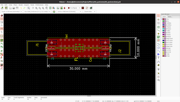
Once you have selected the parts it only the matter of quickly dropping the parts into a KiCAD schematic, laying out the PCB and before you know it, there is a small pile of PCB’s arriving.

As it the way when ordering these types of PCB’s from (JLC PCB)[https://jlcpcb.com], shipping is the biggest expense, even when selecting the cheapest option so I always seem to end up with a lot more PCB than I actually need.
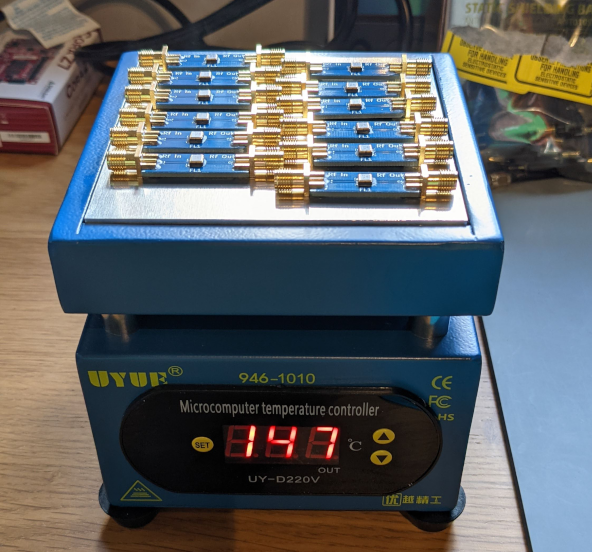
For soldering the board I made us of a Hot Plate that I had recently purchased for the purpose of being able to some small PCB at home in a more controlled way. The Hot plate has a temperature control so I can properly preheat my PCB’s before then increasing the temperate all the way up to ~200 degrees to briefly melt the solder, which made making a larger number of these PCB’s much easier and hopeful with more consistent results.
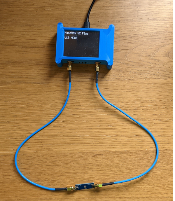
The next stage once I had a few of these Filters made up was to test there performance, for which I used the NanoVNA which I purchased last year. The Nano VNA is a Vector Network Analyser, which allows me to get a better understanding of the filters characteristics, and see if its performance is what I am expecting. While the NanoVNA’s performance is never going to beat the performance of the VNA’s you will find in commercial labs, it’s a great tool for testing out little filters like this that i’m making a home, you can find it on tindie, although a newer model has since been released with an improved frequency range.
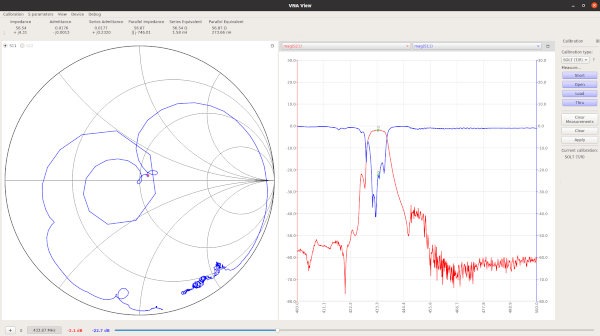
For testing my filters, I hooked up the NanoVNA to my PC and used it with the software NanoVNA QT GUI which allows me to use the NanoVNA from my PC instead of having to use the tiny touchscreen.
The software along with the NanoVNA allows me to clearly see the insertion loss of the filter across the range of frequencies i wanted to measure, as can be shown bellow along with the smith chart showing the measurements.
One thing I was interested in looking into was how consistent all the results were between all the filters that I had built. To measure this between the different filters, I needed to export the results from the NanoVNA for this I attached each of the filters and made use of the ability of the software to measure and then export the S-Parameters in touchstone files for each of the filters.
For analysing and comparing the results of all the different filters I turned to MATLAB, I use MATLAB at work in my day job a lot and have had to have a look at some s-parameter files before at work. I am lucky in that my employer provides me with a Home Use version of MATLAB to install on my home desktop computer, but as I was looking at the data from my laptop I fired up MATLAB Online. MATLAB online allows me to upload my files to “The cloud”, and work from the MATLAB standard IDE from a web browser, without needing to work out how to get it installed on my Macbook with it M1 Processor.
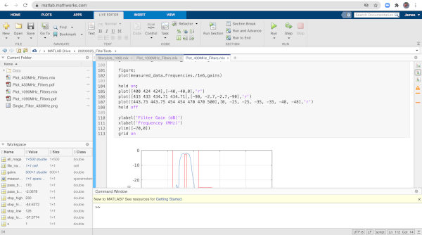
The first step I wanted to do was comparing a set of measurements with the filters specifications, this would allow me to check not only that the filters performance was being dramatically being reduced by any of my bad PCB design and that I was able to plot the results in a meaningful way.
The first step was to load the s-parameter files into MATLAB, and get the magnitude values out from them to be able to plot, this turned out to be possible in only a handful of commands
measured_data = sparameters("Data/433_filter1.s2p");
gains = 10*log10(measured_data.powergain);

figure;
plot(measured_data.Frequencies./1e6,gains)
ylabel('Filter Gain (dB)')
xlabel('Frequencey (MHz)')
ylim([-70,0])
grid on
For the S-Parameters function, you do need to have the correct MATLAB toolbox to load the files, but once there loaded with sparameters() function you get the measured_data object in my case, which provides access to the power gains variable that I wanted to be able to plot, along with the frequencies they were measured at.
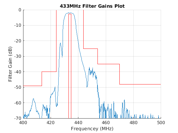
For the plot above I’ve added the red lines which show the performance as quoted in the filter datasheet, with the blue being the values being the values as measured on one of the filters, generated in MATLAB from the S-parameter touchstone file. It shows that mounting on the PCB’s has not resulted in the performance of the filter reducing from the specification. Now I wanted to look at the consistency between all the filters I made, which MATLAB is a great place to look at these variance in the filters gain, and that will be my next step once i’ve measured them all with the NanoVNA.