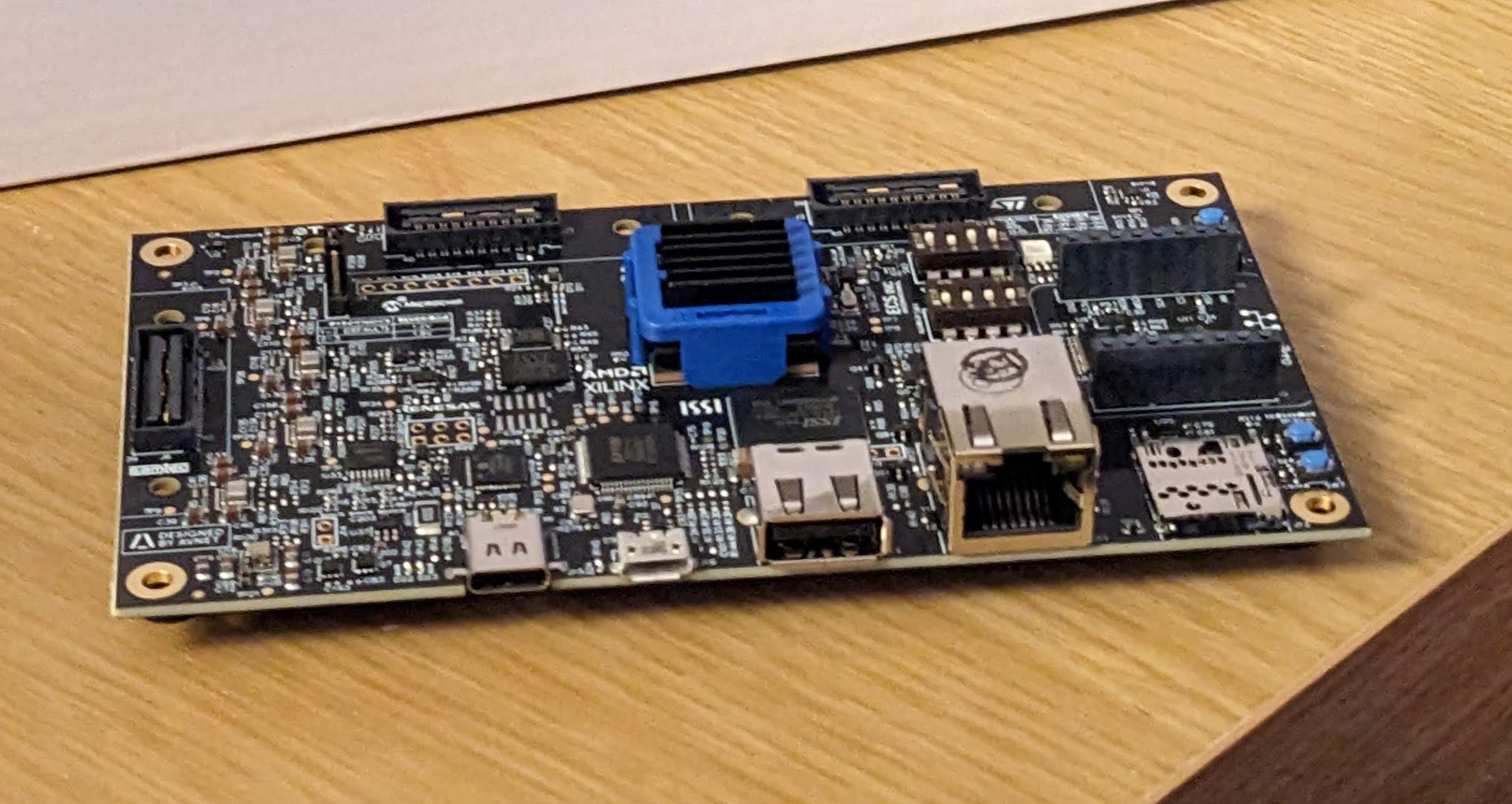
The Avnet CG1 is a low cost Development board built around the Zynq UltraScale+ MPSoC, providing the ZU1CG MPSoC, which works with the free versions of both Vitis and Vivado. Details on the board can be found here.
Setting up the example projects provided by Avnet is relatively simple, with examples of how to set up it with great setup guides here and here. The reference designs which are used in this example are all taken from the following repositories on github:
- github.com/Avnet/bdf (Latest Branch)
- github.com/Avnet/hdl (2022.2 Branch)
- github.com/Avnet/petalinux (2022.2 Branch)
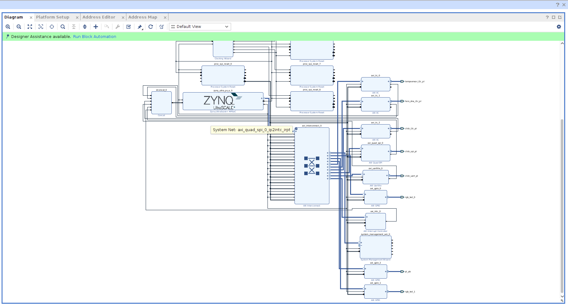
As I was looking to interact with the hardware in this case, I opened up the Vivado Block diagram that was created by the reference designs build script. From this reference design we can have a look to see the that both the LED’s have been connected to GPIO AXI blocks.
The address map screen lets me see where these are connected in the design and the address that will need to be used to access them from within petalinux.
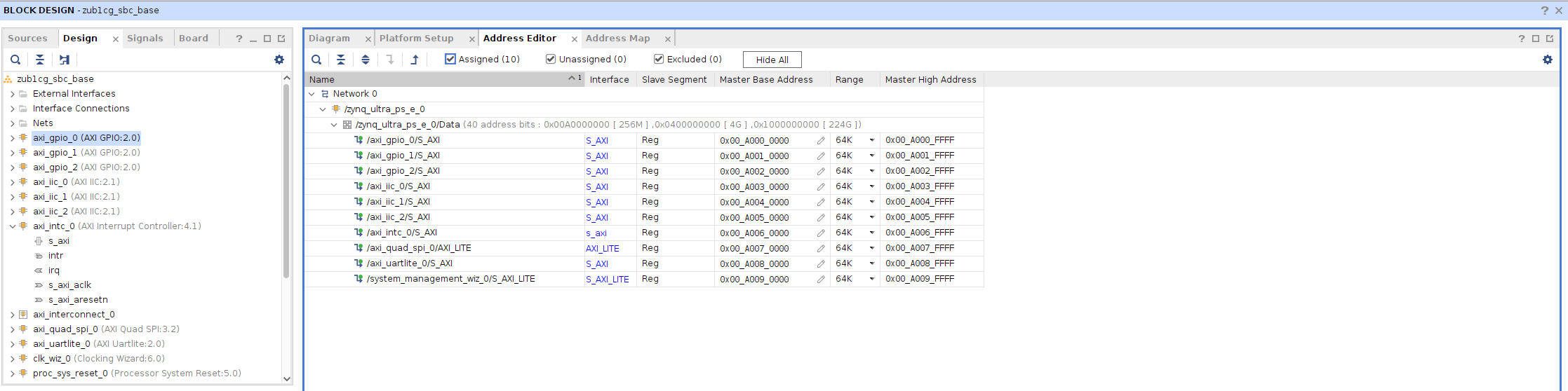
From this we can work out that the following RGB LED’s are connected at the axi memory locations.
| LED | GPIO | Address |
|---|---|---|
| LED[x] | GPIO 0 | 0x00A0000000 |
| LED[x] | GPIO 0 | 0x00A0010000 |
The LED’s are on the GPIO bus, and can be controlled directly from devmem set D5 to RED, by setting the value to 001, using hex in the command line with the devmem command:
devmem 0x00a0010000 32 0x00000001
We can also set to the LED to green by in effect setting the second bit to on which is 0b010 with the same command.
devmem 0x00a0010000 32 0x00000002
With the same command we can also set all the RGB values to be off:
devmem 0x00a0010000 32 0x00000000
The hex value that is input in these commands can there place a number of the Red Green and Blue LED’s in an on or off state, and these are combined to create 8 different possible colors.
While being able to control an RGB from the command prompt is useful, I personally find it much more useful to be able to control the values from within a program, and for use on an embedded system such as an Soc/FPGA like this, I’m going to look to the C programming language.
The task of setting a single value with a program, is one that many people have done before, i did struggle to find any very simple examples, as most try to add a lot of features I wasn’t looking for, but I did find a good example which I cut down to get a minimum example that would set the value of the single LED to be Red:
#include <stdio.h>
#include <stdlib.h>
#include <unistd.h>
#include <sys/mman.h>
#include <fcntl.h>

// based on:
// https://raw.githubusercontent.com/aimeemikaelac/xilinx_zedboard_c/master/src/gpio-dev-mem-test.c

int main(int argc, char **argv) {
	int fd;
	unsigned long long page_addr, page_offset;
	unsigned long long gpio_addr = 0x00A0010000;

	void *ptr;
	unsigned long long page_size=sysconf(_SC_PAGESIZE);


	fd = open("/dev/mem", O_RDWR | O_SYNC);


	page_addr = (gpio_addr & (~(page_size-1)));
	page_offset = gpio_addr - page_addr;
	ptr = mmap(NULL, page_size, PROT_READ|PROT_WRITE, MAP_SHARED, fd, page_addr);


	int value = 1;

	*((int*)(ptr + page_offset)) = value;

	munmap(ptr, page_size);
	close(fd);

	return 0;
}
I stored the example above as led_control.c and copied it onto the sd card using scp over my home network I could then log onto the board using ssh and the default root user name, and build it on the petalinux system
gcc led_control.c -o led_control
Then run from the command line, and watch the LED turn red:
./led_control
Wavedome diagram for the values that the LED’s are being set to
The limitation of this setup is it just turns the LED to red, which while it proves the concept, it does not show the full capabilities of the RGB LED, so I wanted to automate jumping between the 8 possible RGB values that could be displayed using the LED. So by expanding the example to include a loop that cycles though the values 0 to 8, with a short wait inbetween gives this demo of what is possible with this simple setup to cycle though all the values.
#include <stdio.h>
#include <stdlib.h>
#include <unistd.h>
#include <sys/mman.h>
#include <fcntl.h>
#include <unistd.h>

// based on:
// https://raw.githubusercontent.com/aimeemikaelac/xilinx_zedboard_c/master/src/gpio-dev-mem-test.c

int main(int argc, char **argv) {
	int fd;
	unsigned long long page_addr, page_offset;
	unsigned long long gpio_addr = 0x00A0010000;

	void *ptr;
	unsigned long long page_size=sysconf(_SC_PAGESIZE);


	fd = open("/dev/mem", O_RDWR | O_SYNC);


	page_addr = (gpio_addr & (~(page_size-1)));
	page_offset = gpio_addr - page_addr;
	ptr = mmap(NULL, page_size, PROT_READ|PROT_WRITE, MAP_SHARED, fd, page_addr);


	for(int value = 0; value<9; value++){
		printf("%i lED\n",value);
		*((int*)(ptr + page_offset)) = value;
		*((unsigned *)(ptr + page_offset + 8)) = value;

		sleep(1);
	}

	munmap(ptr, page_size);
	close(fd);

	return 0;
}