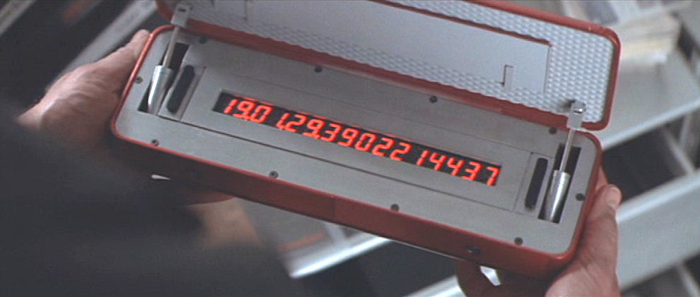
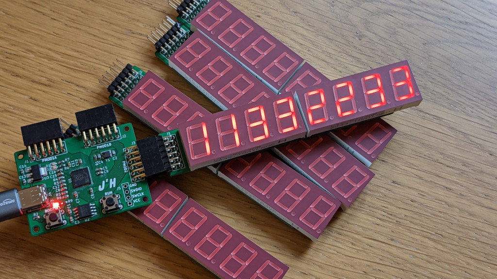
Ive always wanted to build a severn segment display, there is something about the old school style displays that it is hard to beat to display random numerical data like in the movies.
The 7 Segment display that I decided to use, comes with 4 digits per display, and I was looking to combine two per PMod Board, with 8 LED per segment, we don’t have enough pins to be able to control them all. An example of the maximum number of displays that can be controlled by a single PMod, is the display that I got with my iceBreaker FPGA which has two digits, and removes the decimal point to allow multiplexing between the two displays.
Thankfully there are a large number of solutions available to solve this problem, one of which are a range of dedicated chips controlled over a serial link to set seven segment displays.
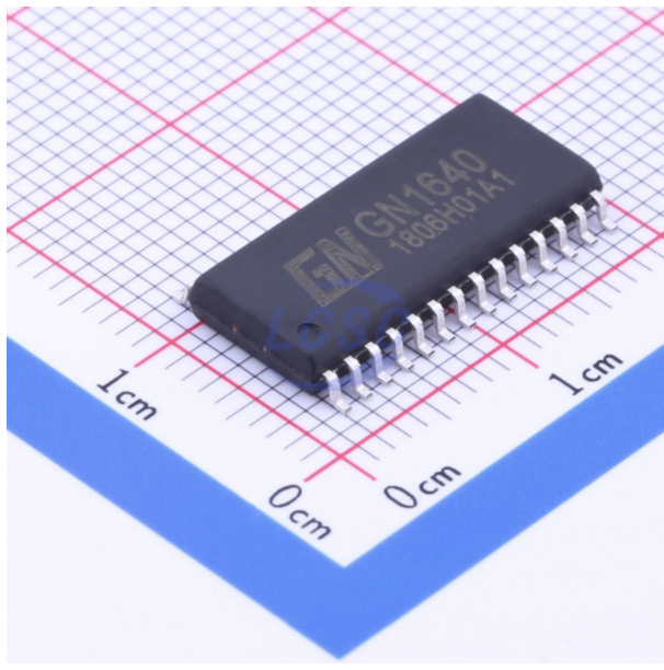
Devices such as the GN Semic GN1640 which is the chip I decided to tag onto an order I was already placing at LCSC Components, at just £0.30 it seemed worth giving it a go. From what I had seen online these components were listed as being very similar to a number of other devices which are listed by other manufactures with similar part numbers such as TM1640, which appears to have a identical datasheet but with the advantage of being available in English.
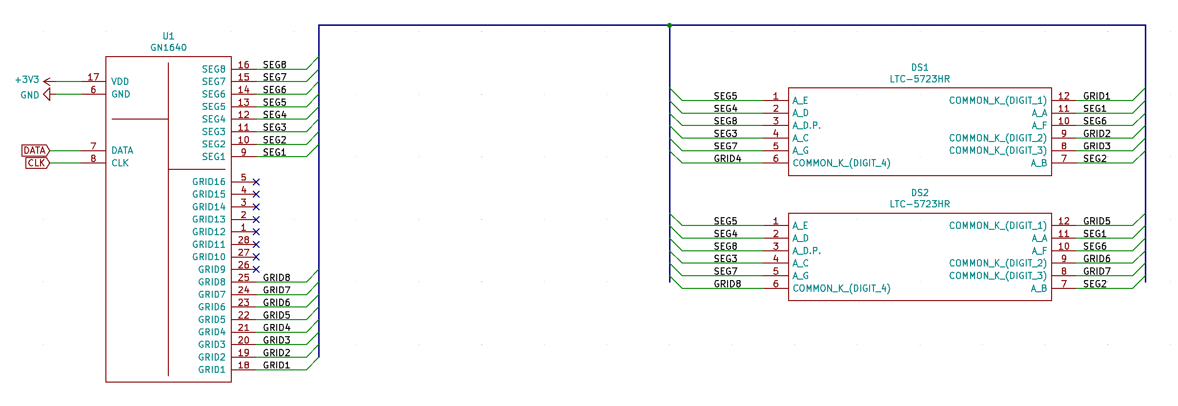
The circuit for these GN1640 chips is relatively simple, with just two input needing to come over the PMod connector, these are a clock signal and a data signal. The circuit for the Seven Segment displays is also relatively simple using a common cathode configuration, which matched my Seven Segment Displays I picked up from Mouser.
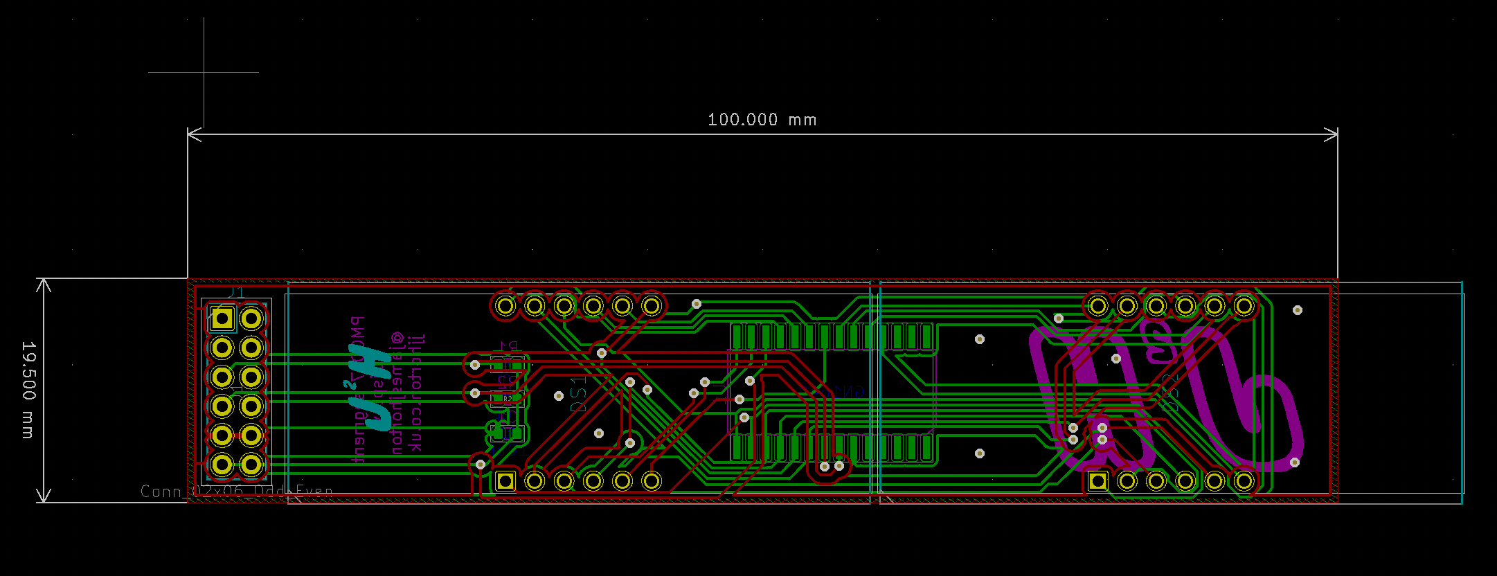
The boards were laid out so that they would fit within the maximum 10x10cm limits of the JLC PCB 2 Layer PCB offer, the issue with this is that each of the displays was 5cm long, taking up the whole length of the PCB, but with all the control pins for the displays being in the centre of each display it was simple to mount the PCB with an overhang at one end leaving room for the PMod connector. The rest of the PCB is a simple 2 layer board, that was designed in KiCad.
With the PCB’s made up, the next challenge was getting some software built up which allowed it to interface with one of my PMod Boards, to start with I used to the RP2040 PMod boards that I had already made. This helps to simplify building up a simple example, as I can use a bit bashing approach to get a simple example.
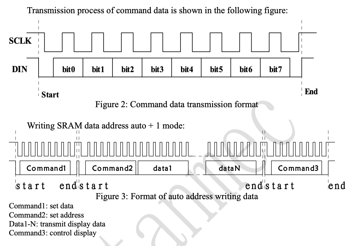
The TM1640 Data Sheet provides a good description of the serial interface, so we can start to build up our functions to control the display, by setting the clk and serial pins either high or low, adding in the required delay as set out in the datasheets timing diagram.
void enable()
{
			//command to turn on the display
			int command1[] = {1,1,1,1,0,0,0,1};
			//initallisation
			gpio_put(pin_data,0);
			sleep_ms(0.2);
			gpio_put(pin_clk,0);
			sleep_ms(0.2);
			//send the bits
			for(int i=0; i < 8; ++i ){
				gpio_put(pin_data,command1[i]);
				sleep_ms(0.2);
				gpio_put(pin_clk,1);
				sleep_ms(0.4);
				gpio_put(pin_clk,0);
				sleep_ms(0.2);
			}
			//end the transmission
			gpio_put(pin_data,0);
			sleep_ms(0.2);
			gpio_put(pin_clk,1);
			sleep_ms(0.2);
			gpio_put(pin_data,1);

			sleep_ms(10);
}
With the display enabled I was then able to start sending data, this follows a similar design pattern with a function taking in the address and data, to trigger a series of short delays followed by setting the clock and data pins either high or low to transmit the data.
void txData(uint8_t pos, uint8_t data)
{
			uint8_t addr = 0b11000000 + pos;

			gpio_put(pin_data,0);
			sleep_ms(0.2);
			gpio_put(pin_clk,0);
			sleep_ms(0.2);

			for(int i=0; i < 8; ++i ){
				gpio_put(pin_data,(addr >> i) & 1U);
				sleep_ms(0.2);
				gpio_put(pin_clk,1);
				sleep_ms(0.4);
				gpio_put(pin_clk,0);
				sleep_ms(0.2);
			}

			for(int i=0 ; i < 8; ++i ){
				gpio_put(pin_data,(data >> i) & 1U);
				sleep_ms(0.2);
				gpio_put(pin_clk,1);
				sleep_ms(0.4);
				gpio_put(pin_clk,0);
				sleep_ms(0.2);
			}
			gpio_put(pin_data,0);
			sleep_ms(0.2);
			gpio_put(pin_clk,1);
			sleep_ms(0.2);
			gpio_put(pin_data,1);
}
The next challenge now I’m able to send data to the display using simple functions, is to look at turning the control functions into a C++ object, and then look at putting the display to a practical use. Another route to look at is setting up the PIO state machine to work with the display and possibly build a simple example that can also work with my Ice Breaker FPGA.