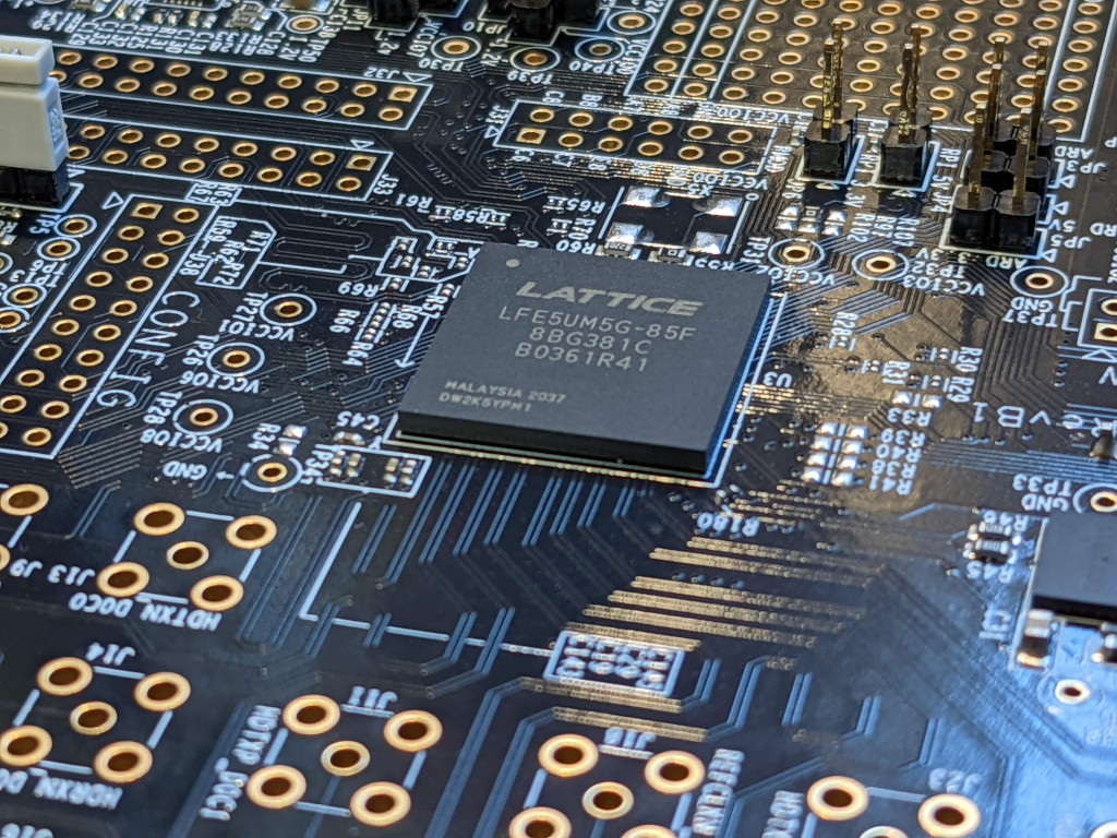
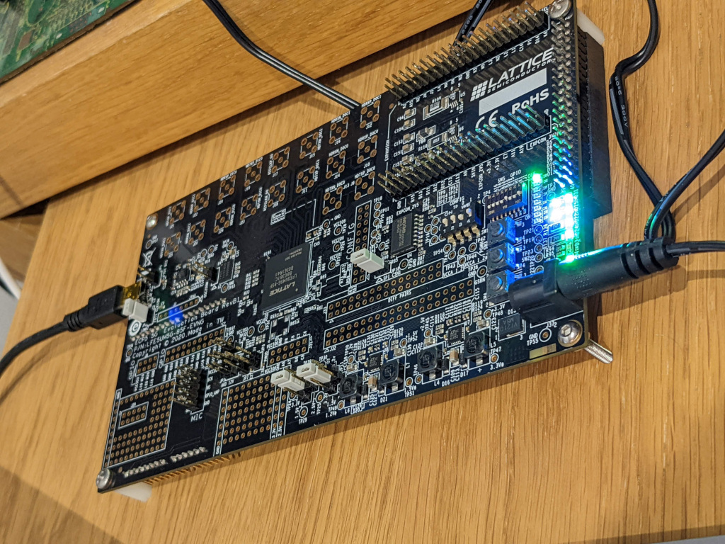
In this post I am recording how I got my first design onto the ECP5 Development board that I recently purchased. This devboard makes use of the LFE5UM5G FPGA, on a pcb, with lots of IO broken out including the SERDES Pins. For this example, I am using the on-board 8 LED’s, and an example that I originally used with my icebreaker board and an LED PMod.
As a Macbook Air user, with its M1 processor, sometimes means getting the right tools can be a challenge. Thankfully unlike the main vendor tools where using a Macbook for development is a none starter, the open source tools can be installed with only a few commands. I’m using the tools from homebrew that are available on github which makes installing with homebrew really easy:
brew tap ktemkin/oss-fpga
brew install --HEAD project-trellis yosys nextpnr-trellis
The actual code I’m going to use to get started is a few simple lines of Verilog, with a clock divider that aims to trigger roughly once a second, before shifting the output LED one to the left in the line of LED’s. The only input is CLK and the only output is the array of 8 LED’s.
`default_nettype none

module blinky(CLK, LED);
	input 	wire 			CLK;
	output 	wire 	[7:0]	LED;

	parameter 	WIDTH=25;

	reg 	[WIDTH-1:0]		counter;
	reg 	[7:0]			display;

	initial counter = 0;
	initial display = 8'b00000001;

	always @(posedge CLK)
	begin
		counter <= counter +1'b1;

		if (counter[WIDTH-1] == 1)
		begin
			// When the counter reaches top value shift the LEd accross one
			counter <= 0;
			if (display== 8'b10000000)
				display <= 8'b00000001;
			else
				display <= display << 1;
		end
	end

	assign LED = display;
endmodule
With the example outlined in Verilog the first job is complying the design using Yosys, this tools takes the Verilog design and converts it into a json design in elements that can be placed onto the FPGA. The synth_ecp5 script is used for compiling the design, outputting the resulting design in the blink.json file
yosys -p 'synth_ecp5 -top blinky -json blink.json' blinky.v
Now we have our design compiled into elements that can be placed onto an FPGA, I need a file to tell what the designs input and outputs needs to be physicially connected to. This file is an .lpf file, which contains the Pin names and the sites that they need to be connected to on the FPGA package
LOCATE COMP "CLK" SITE "A10";
IOBUF PORT "CLK" IO_TYPE=LVCMOS33;

LOCATE COMP "LED[0]" SITE "A13";
LOCATE COMP "LED[1]" SITE "A12";
LOCATE COMP "LED[2]" SITE "B19";
LOCATE COMP "LED[3]" SITE "A18";
LOCATE COMP "LED[4]" SITE "B18";
LOCATE COMP "LED[5]" SITE "C17";
LOCATE COMP "LED[6]" SITE "A17";
LOCATE COMP "LED[7]" SITE "B17";
With our pin definition file ecp5sum-eval.lpf, we can then feed this in with the design json fileblink.json, to build our bit stream. For this we need to specify the device --um5g-85k and it’s package --package CABGA381
nextpnr-ecp5 --um5g-85k --package CABGA381 --json blink.json --lpf ecp5sum-eval.lpf --textcfg blink.config
Now the design is compiled, I can use ecppack to build the bitstream file, in this example I use the --compact flag, which reduces the bitstream size with compression and helps make it quick to upload to our board.
ecppack --compress --bit blink.bit blink.config
For loading the design onto the development board i’m using the Open FPGA Loader my main reason for using this is that it is simple to install on my M1 Mac with a single line
brew install openfpgaloader
With the software installed and the Devboard hooked up to the USB port, I can then check that the ecp5 development board is detected, using the detect command:
openfpgaloader --detect
Jtag frequency : requested 6.00MHz   -> real 6.00MHz
index 0:
        idcode 0x1113043
        manufacturer lattice
        family ECP5
        model  LFE5U-85
        irlength 8
Now we know that that the board is connected, and that it can see the correct device that we are expecting, we just need to send the design over onto the board. There are two methods we can do this, the first is loading into SRAM. Loading into SRAM is quicker, but it is volatile, so will disappear once the power is disconnected:
openfpgaloader -b ecp5_evn blink.bit
The second option is writing to flash, which is non-volatile, this takes a bit longer but will be loaded each from the flash each time the power is applied to the board:
openfpgaloader -b ecp5_evn -f blink.bit
With the design all loaded in, that completes this post, next up is getting a few simple designs hooked upto the PMOD connect on the board. Then at some point I will be hopefully taking a look at the SERDES options on this board, as i’ve got a few ideas I would like to have a play around with.