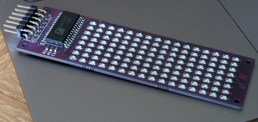
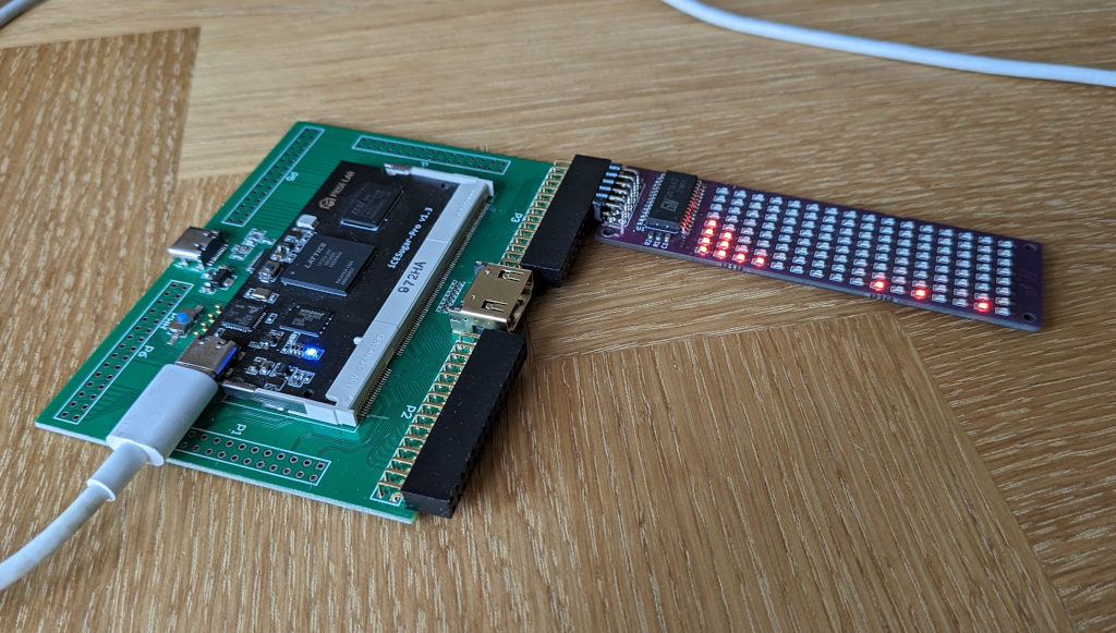
After finally finishing of the LED Array PMod Board example, it was also long over due getting an example up and running with the FPGA Development Board. For the FPGA I was aiming to create a design that can be controlled over serial rather than running locally like the software based design.
The first thing to consider is the sub system that controls sending the data, for this to work as intended we need a system clock which is derived from the FPGA Clock, this is used to control the rate at which data is sent out to the GN1640 chip that controlls the LED’s
    // clock rate for calculating the clock divider
	parameter 	clk_in_rate_hz = 12_000_000;
	parameter	clk_pixel_rate_hz = 1_000_000;
	parameter 	clk_divider_count = (clk_in_rate_hz/clk_pixel_rate_hz)/2;
    parameter   clk_count = clk_divider_count[15:0];

	//clock divider for setting the rate that the state can change
	always @(posedge clk) begin
		if (counter < clk_count )
			begin
                if ((valid == 1) & (busy == 0))
                    begin
                    counter <= 0;
			        sys_clk <= ~sys_clk;
                    end
                else
                    counter <= counter + 1'b1;
			end
		else
            begin
			    counter <= 0;
			    sys_clk <= ~sys_clk;
			end
	end
Using this sys_clk we can start building up the control for sending the data is based on a simple state machine that works though sending the data to the PMod board from the values that have been passed in.
	always @(posedge sys_clk) begin
		case(state)
			IDLE:
				begin
                    //idle is both clk and data high
                    data_out    <= 1;
                    clk_out     <= 1;

                    //change to start tx if data avalible
                    if (data_ready == 1)
                    begin
                        state <= START_1;
                    end
                end
            START_1:
				begin
                    state <= START_2;

                    // set data and clk to indicate the start
                    data_out    <= 0;
                    clk_out     <= 1;

                    //initalise the bit counter
                    bit_counter <= 0;
                end
            START_2:
				begin
                    state <= DATA_1;

                    // set data and clk to indicate the start
                    data_out    <= 0;
                    clk_out     <= 0;

                    //initalise the bit counter
                    if( my_value[7:0] == 8'b11111111)
                        bit_counter <= 8;
                    else
                        bit_counter <= 0;
                end

            DATA_1:
				begin
                    state <= DATA_2;

                    data_out <= my_value[bit_counter];
                    clk_out <= 0;
                end
            DATA_2:
				begin
                    state <= DATA_3;

                    data_out <= my_value[bit_counter];
                    clk_out <= 1;
                end
            DATA_3:
				begin
                    state <= DATA_4;
                    data_out <= my_value[bit_counter];
                    clk_out <= 1;
                end
            DATA_4:
				begin
                    if(bit_counter < 15)
                        begin
                        state <= DATA_1;
                        bit_counter <= bit_counter + 1 ;
                        end
                    else
                        begin
                        state <= FINISH_1;
                        bit_counter <= 0;
                        end

                    data_out <= my_value[bit_counter];
                    clk_out <= 0;
                end

            FINISH_1:
				begin
                    // set data to indicate end of bits to be written
                    data_out    <= 0;
                    clk_out     <= 0;
                    // the next state is Idle
                    state <= FINISH_2;
                end
            FINISH_2:
				begin
                    // set data to indicate end of bits to be written
                    data_out    <= 0;
                    clk_out     <= 1;
                    // the next state is Idle
                    state <= FINISH_3;
                    fin_count <= 0;
                end
            FINISH_3:
                begin
                    // set data to indicate end of bits to be written
                    data_out    <= 1;
                    clk_out     <= 1;
                    // the next state is Idle

                    fin_count <= fin_count + 1;
                    if(fin_count < 128)
                        state <= FINISH_3;
                    else
                        state <= IDLE;
                end

        endcase
    end
This state machine is what forms the backbone of the design, which is captured in the writepixels.v file, segregating the design from the rest of the design. At the top level we have a top.v file which connects the designs other components together, including the serial link which is a design I have used before. The top level provides the state machine that feeds the the values to the pixelwriter. The 16 lines are set one after another, before then being triggered by the pps signal which would normally trigger the display update once per second.
    // state Machine for setting display
    // State Machine States
    parameter 	IDLE 	    = 0;
	parameter 	INITDISPLAY	= 1;
    parameter 	PAUSE	    = 2;
    parameter 	SETDISPLAY	= 3;

    always @(posedge CLK) begin
		case(system_state)
			IDLE:
            begin
                if(pps == 1)
                    system_state <= INITDISPLAY;

                valid <= 0;
            end

            INITDISPLAY:
            begin
                // if the display is not busy set the input
                if((busy == 0) & (valid == 0))
                begin
                    value <= 8'b10001001;
                    valid <= 1;
                    system_state <= PAUSE;
                    byte_count <= 0;
                    pos <= 8'b11111111;
                end
                else
                    valid <= 0;

                pause_counter <= 0;
            end

            PAUSE:
            begin
                valid <= 0;
                pause_counter <= pause_counter + 1;
                if(pause_counter < (clk_in_rate_hz/1000) )
                    system_state <= PAUSE;
                else
                    system_state <= SETDISPLAY;
            end

            SETDISPLAY:
            begin
                // if the display is not busy set the input
                if((busy == 0) & (valid == 0))
                begin
                    /* verilator lint_off WIDTH */
                    pos <= 8'b11000000 + byte_count;
                    /* verilator lint_on WIDTH */

                    value <= tx_value[byte_count];
                    valid <= 1;

                    if(byte_count<15)
                    begin
                        system_state <= SETDISPLAY;
                        byte_count <= byte_count + 1;
                    end
                    else
                        system_state <= IDLE;
                end
                else
                    valid <= 0;
            end
        endcase
    end
With the state machines controlling the output to the LED array from the tx_value array, the only missing stage is setting the values from the serial insterface. As the display is being updated slowly i’m only using a single display buffer, so the values that are read in over the serial link are ready into this, the readin of data is triggered based on the character A which triggers the start of reading 16 8 bit characters which are put into the tx_value. which is completed with a simple state machine.
//uart statemachine
parameter 	WAIT 	    = 0;
parameter   START_CHAR  = 1;
parameter 	RECEIVING	= 2;

always @(posedge CLK) begin
    //check if there is valid serial data

    case(data_state)
        WAIT:
            begin
                data_state <= START_CHAR;
                uart_counter <= 0;
            end

        START_CHAR:
            begin
                if(uart_valid == 1) begin
                    if(uart_value == 8'b01000001) //check for 'a'
                        data_state <= RECEIVING;
                    else
                        data_state <= START_CHAR;
                end
            end

        RECEIVING:
            begin
            if(uart_valid == 1) begin
                uart_counter <= uart_counter + 1;
                tx_value[uart_counter][7:0] <= uart_value[7:0];
                if(uart_counter < 15)
                    data_state <= RECEIVING;
                else
                    data_state <= WAIT;
                end
            end
    endcase
end
With the details of how to get data sent over, to start with for testing a simple bit of python which can send over some values to display on the LED Array, this uses the serial package to send the values out. This can be acheived in just a few lines of code:
import serial
import io

ser = serial.Serial('/dev/tty.usbmodem1102', 115200 ,timeout=0.25)

ser.write(b'A')
ser.write(bytes([1,3,7,15,31,63,127,1,3,63,3,1,3,1,3,1]))
ser.close()
While the setting of the values using a generic static values proves that the FPGA design works, I wanted to demonstrate something that is more dynamic. For this I use the audio input on my laptop and generate a frequency response on the screen which updates as data is received.
For collecting the audio values, I make use of pyaudio to collect one channel audio from the laptops microphone and read back a chunk.
import pyaudio

CHUNK = 1024
FORMAT = pyaudio.paInt16
CHANNELS = 1
RATE = 44100
RECORD_SECONDS = 5

p = pyaudio.PyAudio()

stream = p.open(format=FORMAT,
                channels=CHANNELS,
                rate=RATE,
                input=True,
                frames_per_buffer=CHUNK)

data = stream.read(CHUNK)
The values that come from the audio stream need to be converted into something which can be displayed on the LED Array, for this simple example we use as FFT to do a conversion to the Frequency domain, then carry out a logorithum and scale to fit the normal range within the 8 pixel hight of the display.
values = np.frombuffer(data, np.int16)
values = values - np.mean(values)
largest[a] = np.max(values)
freq_amp = np.log2(np.abs(np.fft.fftshift(np.fft.fft(values,32))))[16:32]
upscale = 1
in_scaled = (freq_amp*upscale)-4
tx_amp = np.power(2,np.abs(np.array(in_scaled, dtype=np.int8)))-1

ser.write(b'A')
ser.write(bytes(tx_amp))
The final part of the example then uses the same serial commands as before to send the values to the display, which can be run in a loop to display the changing audio levels received.
The complete code example is stored in the GitHub repo which includes the completed code and make scripts for building and programming the FPGA.