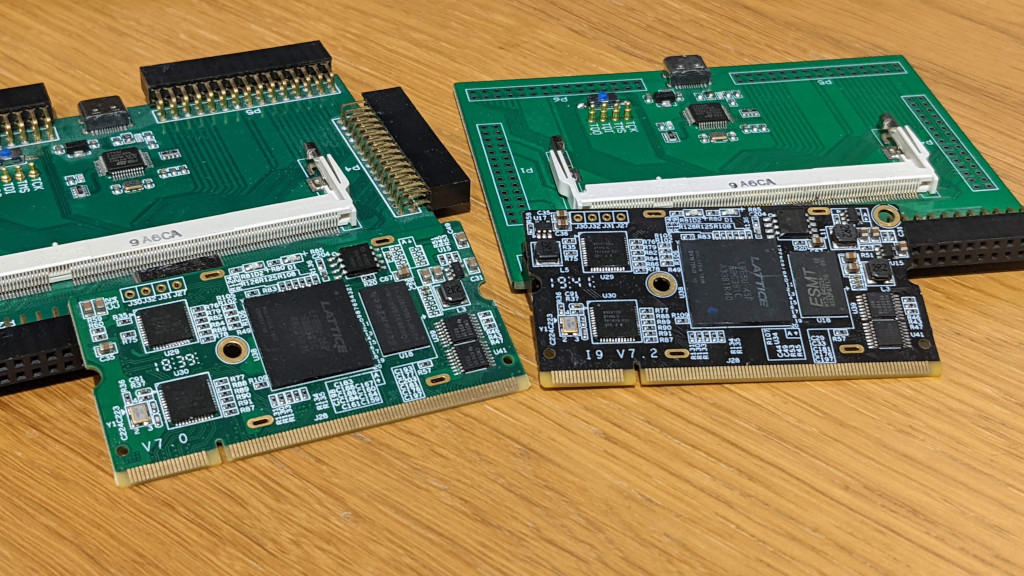
Having previously purchased a several FPGA development boards, this is the latest one for working with both Yosys and Next-pnr, an open source FPGA tool chain. I have brought 2 of these other boards which are both based around the color light modules, these boards are avalible as both the Lattice ECP5 FPGA Colorlight i5 Development Board and Lattice ECP5 FPGA Colorlight i9 Development Board. They include a breakout board that allows you to connect PMod Modules, HDMI (Which i’ve never used) and a USB-C port that allows the connection of a computer to do the programming and serial connections. The breakout board is important for these versions, as it includes everything you need to program the FPGA boards, which can’t be done when they aren’t in the breakout board.
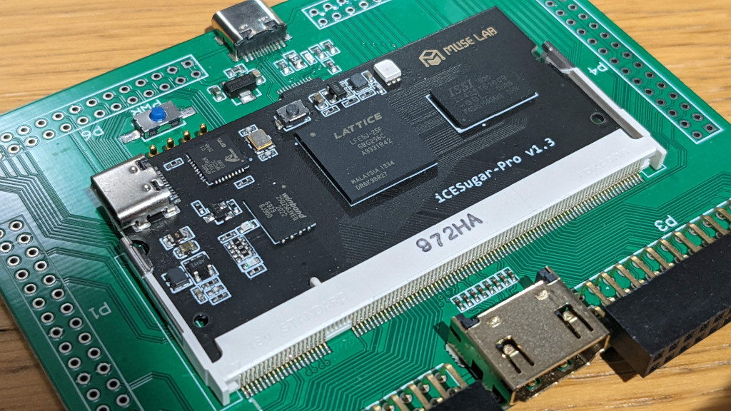
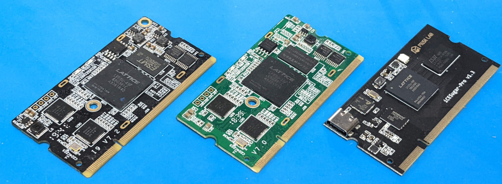
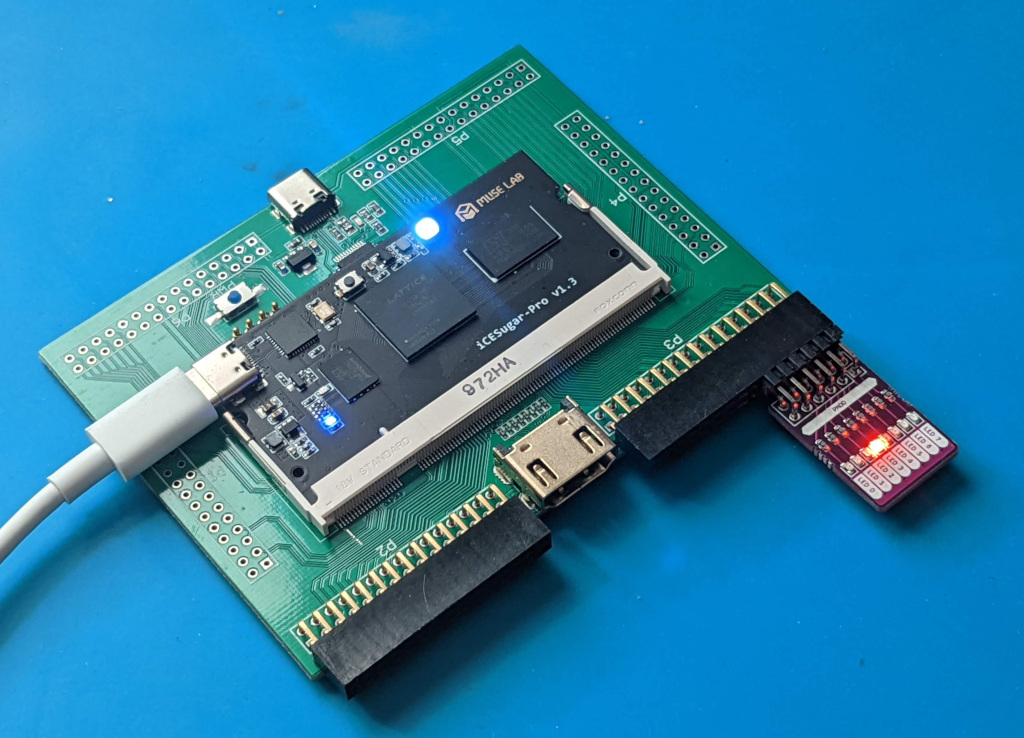
The Ice Sugar Pro is a variation of these boards, it makes use of the same breakout board with the PMod breakouts, but uses a custom FPGA board rather than the modules that are designed for driving the LED Matrix Boards. This means it has some extra features that are specifically designed to make working with it a bit easier, the main one for me is the USB-C port on the FPGA module itself, which provides the debug/programming interface as well as a serial port directly on the FPGA board. Where as my other board don’t have the direct programmability, only reprogrammable with the breakout board. This means it should make life easier when I start thinking about building and designing my own custom breakout board.
The pin out iCE Sugar Pro host board which is available from the sellers Git Repository is shown bellow, while I do sometimes fid it tricky to map the pins out using this diagram, it is much easier than using the schematic.
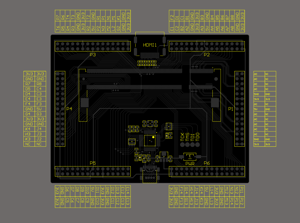
Unfortunately the connections are different to the other Colorlight i5 and i9 modules, as the FPGA is in a different package.
Getting a simple FPGA example up and running, displaying a simple pattern on an LED PMod board. The code for this is taken from another project, but is just a case of displaying an LED that is bit shifted across the 8 LED’s
`default_nettype none

module blinky(CLK, LED);
	input 	wire 		CLK;
	output 	wire 	[7:0]	LED;

	parameter 	WIDTH=25;

	reg 	[WIDTH-1:0]		counter;
	reg 	[7:0]			display;

	initial counter = 0;
	initial display = 8'b00000001;

	always @(posedge CLK)
	begin
		counter <= counter +1'b1;

		if (counter[WIDTH-1] == 1)
		begin
			// When the counter reaches top value shift the LEd accross one
			counter <= 0;
			if (display== 8'b10000000)
				display <= 8'b00000001;
			else
				display <= display << 1;
		end
	end

	assign LED = display;
endmodule
The pinout for the FPGA needs to be mapped to the output pins which the port that the PMod board is connected to, these are stored in our icesugarpro.pcf file. This not only tells the FPGA where the LED’s are connected to, but also where our only input is connected the clock signal as CLK on pin P6, the pin for this is taken directly from the schematic from the sellers Git Repository and a number of key pin mappings are provided in the top level README.
LOCATE COMP "CLK" SITE "P6";
IOBUF PORT "CLK" IO_TYPE=LVCMOS33;

LOCATE COMP "LED[0]" SITE "T6";
LOCATE COMP "LED[1]" SITE "P7";
LOCATE COMP "LED[2]" SITE "R5";
LOCATE COMP "LED[3]" SITE "R6";
LOCATE COMP "LED[4]" SITE "R4";
LOCATE COMP "LED[5]" SITE "T4";
LOCATE COMP "LED[6]" SITE "R3";
LOCATE COMP "LED[7]" SITE "T3";
The commands for building the FPGA image, first up is Yosys for the RTL synthesis from our Verilog file:
yosys -p 'synth_ecp5 -top blinky -json blinky.json' blinky.v
Then nextpnr for completing the job of Place and Route of our design onto the FPGA’s resources:
nextpnr-ecp5 --25k --package CABGA256 --json blinky.json --lpf icesugarpro.pcf --textcfg blinky.config --freq 100
Packing up the image and transfering it to the fpga, the tool ecppack is used to convert the config file into the format that will be loaded onto the FPGA. One key feature that I am using here is the --compress flag, this compressed the bit file and dramatically reduces the programming time for the board. In this case it reduces it from to less than 4 seconds
ecppack --compress --bit blinky.bin blinky.config
ecpdap program --freq 5000 blinky.bin
Rather than just programming the FPGA directly, we can also upload the design to the on-board flash, so that when we power cycle the FPGA it still loads our design.
ecpdap flash unprotect
ecpdap flash write --freq 5000 blinky.bin
The first line doesn’t aways need to be run, by default the flash should be unprotected, but I found sometimes it would fail to program, and with this quick simple command it works a lot more reliably.
A full copy of the code for this blink example can be downloaded from github. My Next challenge with this board is to have a look at the RGB LED, and see if I can get a program together to show the full range of colors with it, before looking into building a custom host board to work with it.