I have been looking to put together a GPS board for a while, as I had a few ideas for upgrading a project with realtime time information, and a few things that I could try out if I had location or time data, as well as an accurate timing pulse source. While there are actually plenty of options for just buying a pre-made PMod module, I decided I would be better of giving it a go myself as I wanted a few of them and that could make it cheaper to build my own if I needed a few.
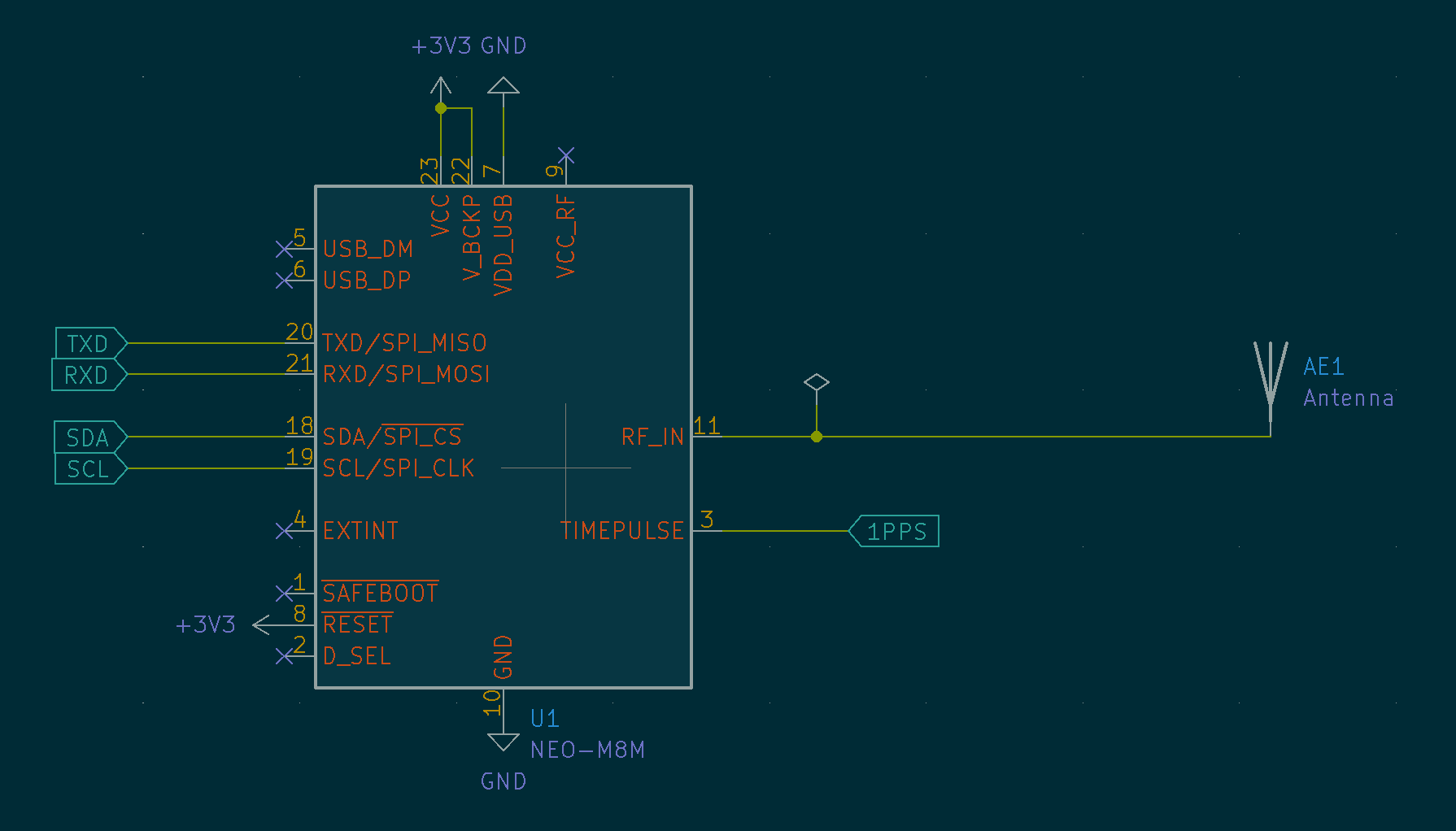
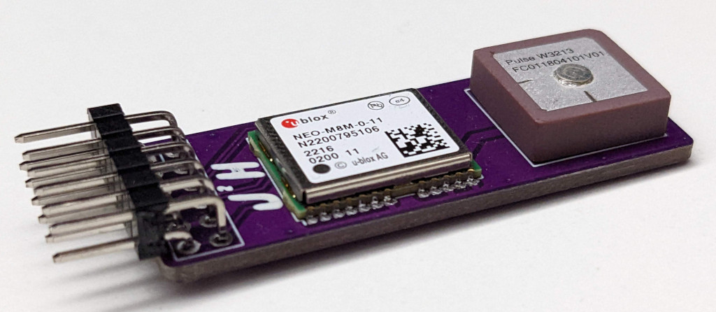
As I didn’t want to reinvent the wheel the easiest way to create what needed was to use a ublox module, and then mount an antenna on a PCB, and as simple as that it is job done. This module would give me a nice simple serial interface to the GPS data, allow me to get access to the time pulse data and is the lowest risk way to create what I needed.
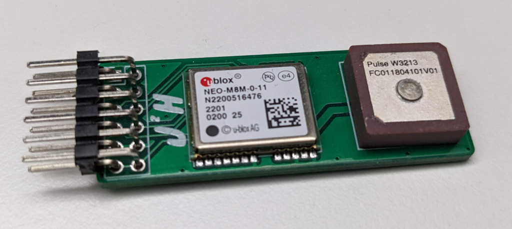
The first board had a minor error, in that I had connected the serial TX/RX wires the wrong way round, so I couldn’t connect to my (RP2040 PMOD Board)[https://github.com/jjhorton/Pico_Pmod] that I planned to test without using breakout wires. So while I re-spun the board with the serial connection the right way round I hooked up the board to an iceBreaker FPGA Board.
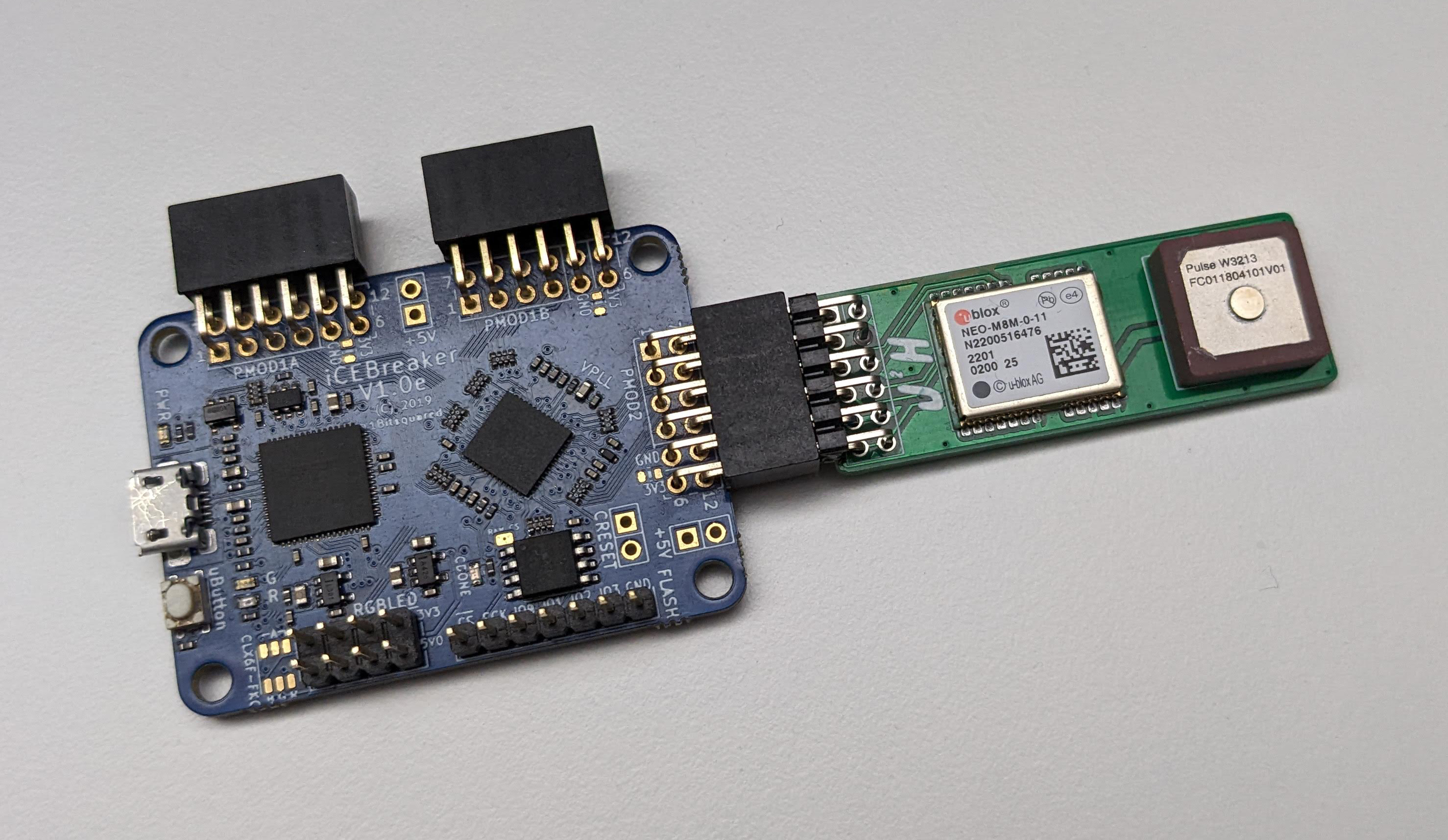
By using the FPGA board, I can create a simple thru wire design to out work as a serial device, so i can check the output from the serial output and that the one PPS is working as expected. With serial connected straight though the design, and then the 1 PPS signal broken out to an LED, on the icebreaker Development board I was using.
module thruwire(clk, in_tx, in_rx, pmod_tx, pmod_rx, pps, ledr, ledg);
	input clk;
	input in_rx;
	output in_tx;

	input pmod_rx;
	output pmod_tx;

	input pps;

	output ledr;
	output ledg;

	reg led;
	always @(posedge clk)
		led <= !led;

	assign ledg = led;

	assign pmod_tx = in_rx;
	assign in_tx = pmod_rx;
	assign ledr = !pps;

endmodule
This design is then built with Yosys, and next-pnr, to allow the GPS board to be tested, confirming the messages were arriving at the PC and were giving the location as expected. This is a great point to get to in confirming the design works and that the antenna is suitable which were the main risks with this design. While there is more testing I want to do with the FPGA, but the new PCB’s arrived so it was time to get some more components on order and test it out with the RP2040 PMod Board.
With the functionality of the GPS module itself, it was in part a case of confirming the behavior of the board, the first piece of data I was interested in was the location data, this is provided in the standard GPS messages that the uBlox produces over the serial messages, the real task here is decoding these messages and finding a way to display them.
The first task here on the RP2040, is to read the message from the UART as they become available, for that in this case we are reading the sting, from the characters one at a time until reaching an end of line character, once there we can check the message type using the first 6 characters, in this case we are looking for “$GNRMC”, the details of the different GPS messages can be found online.
while (1) {
    // send any chars from stdio straight to the host
    if (uart_is_readable(UART_ID)>0) {
        char c = uart_getc(UART_ID);
        if (c < 128) {
            if(c == '\n')
            {
               if(strncmp(message,"$GNRMC", 6)==0) {
                    printf("found GNRMC\n");
                    printf("%s\n",message);
Once we have the message, we can then look to extract the values, and convert them to something I can then use, for this I can just work my way though the comma separated list of values that makes up the list, to find the points in the list that contain the lat and lon values that I am looking for.
for( int i=0; i < char_count; i++){
    if(message[i] == ','){
        comma++;
        if(comma == 3){
            s_lat = i + 1;
        }
        if(comma == 5){
            s_lon = i + 1;
        }
    }
}
With these values, its then just a case of taking the values from the string and turning them into a decimal number, as the values are in the format Latitude DDmm.mm, and Longitude DDDmm.mm, so these decimal and minute values need to be converted into a fully decimal value at the same time
double lat_deg = 10*(message[s_lat]-'0') + (message[s_lat+1]-'0');
double lat_min = 10*(message[s_lat+2]-'0') + (message[s_lat+3]-'0')+ 0.1*(message[s_lat+5]-'0') + 0.01*(message[s_lat+6]-'0');+ 0.001*(message[s_lat+7]-'0');
double lon_deg = 100*(message[s_lon]-'0') + 10*(message[s_lon+1]-'0') + (message[s_lon+2]-'0');
double lon_min = 10*(message[s_lon+3]-'0') + (message[s_lon+4]-'0')+ 0.1*(message[s_lon+6]-'0') + 0.01*(message[s_lon+7]-'0');+ 0.001*(message[s_lon+8]-'0');
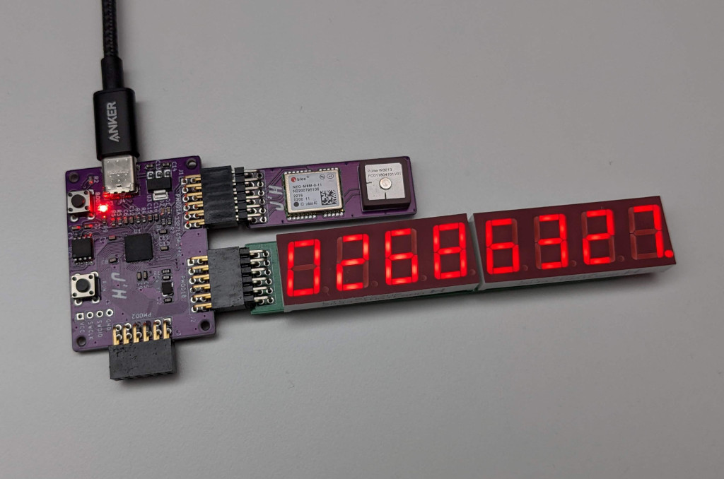
With those values being displayed, it is then a simple case of outputting them to a display, which today is my severn segment displays I made last year.
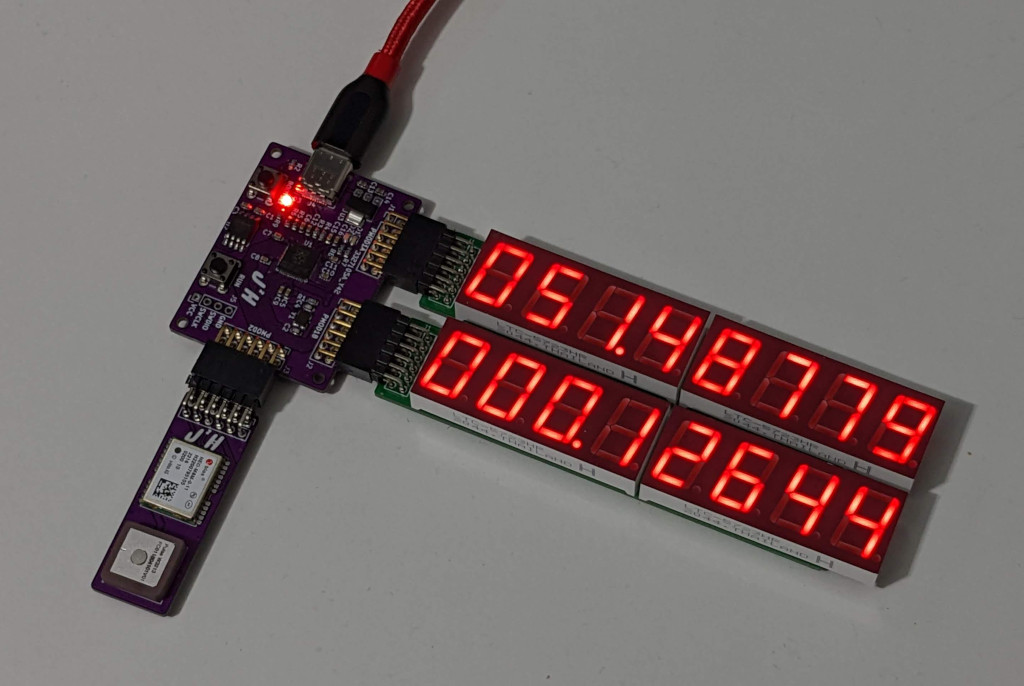
One limitation of these displays is that I never coded the ability to display negative values, to so cannot show them on here at the moment as should be the case, but I will have to update that at some point soon.
The next challenge to be completed here is to update my Countdown timer, to use the GPS board as the source for its timing information rather than relying on a PC to provide it.