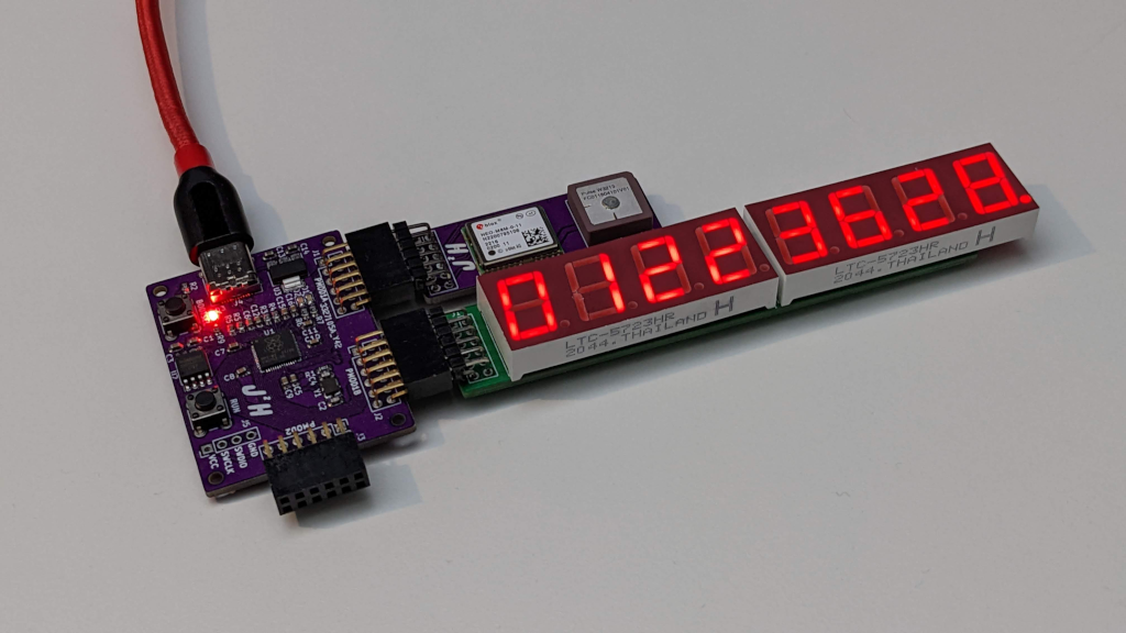
The countdown timer that I created last year, which used my custom RP2040 Pmod board with the PMod Severn Segment Display I had also created, was in need of an upgrade. The main aim of this project was to replace the Raspberry Pi Zero that provided the time data to what was just a display made of my custom hardware, and turn it into something that can run automonously, by getting that time data from a GPS reveiver.
The main advantage of using GPS data for this is that by using a GPS receiver we have a high accuracy timing data source, now I wanted to understand how I can make the display update as accurate as possible using this new timing source so I needed to measure how well my initial setup worked, so I built a test setup.
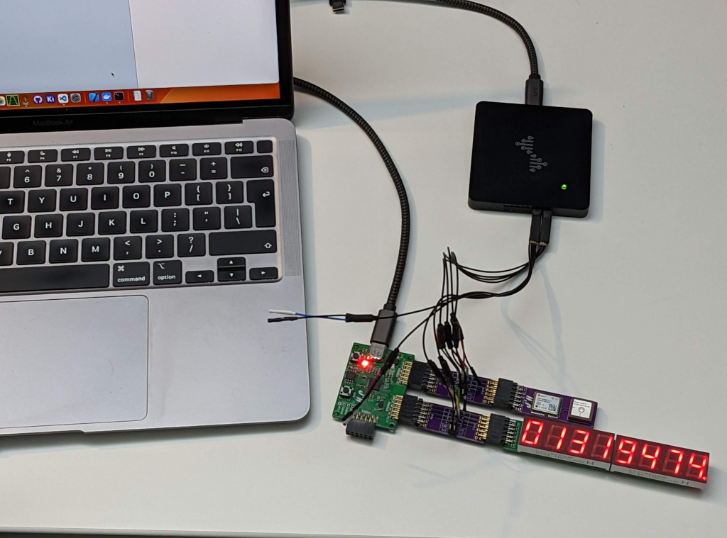
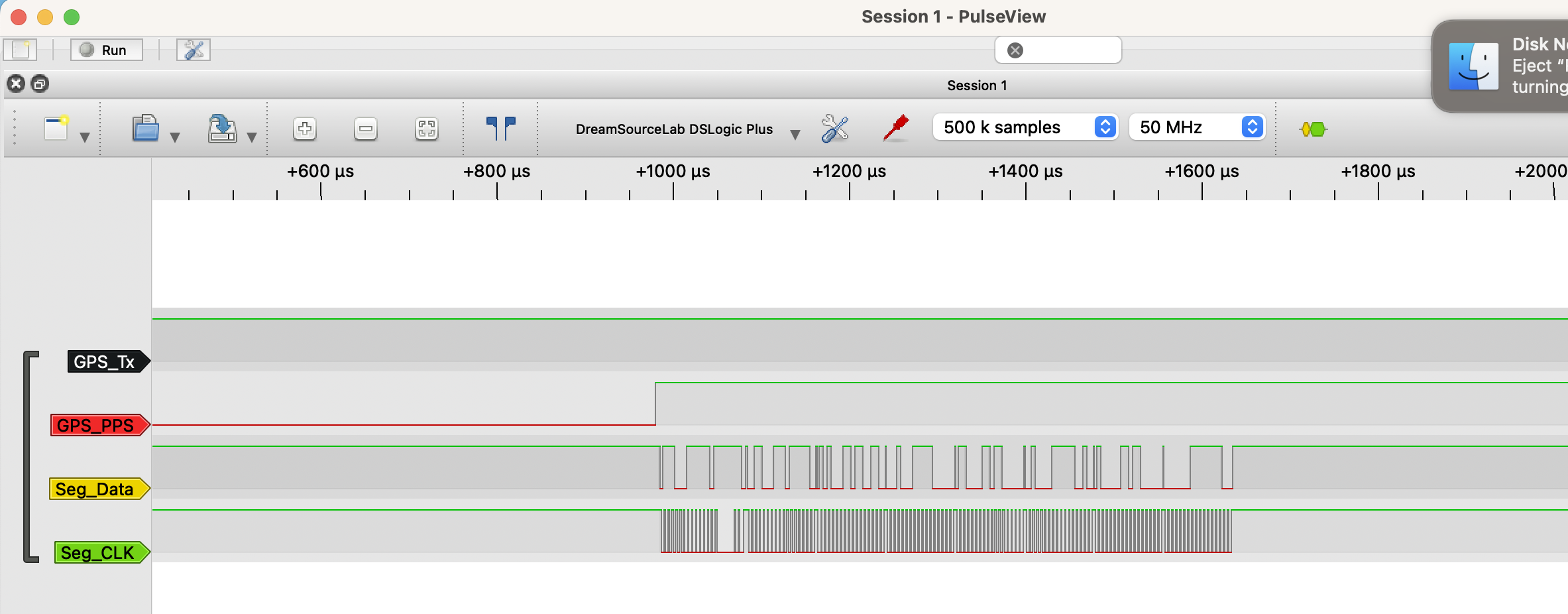
With this test setup, using some PMod Breakout Boards, I could monitor the Serial Data and 1 PPS from the GPS, as well as the Clock and Data lines to the PMod 7 Segement display. By monitoring all these signals at the same time I could monitor the progress of the data through the system, the 1 Pulse Per Second (PPS) signal makes the absolute point that a second begins and the time at which the data is valid for, we can then reference the delay in which it takes from the time information to reach the display.
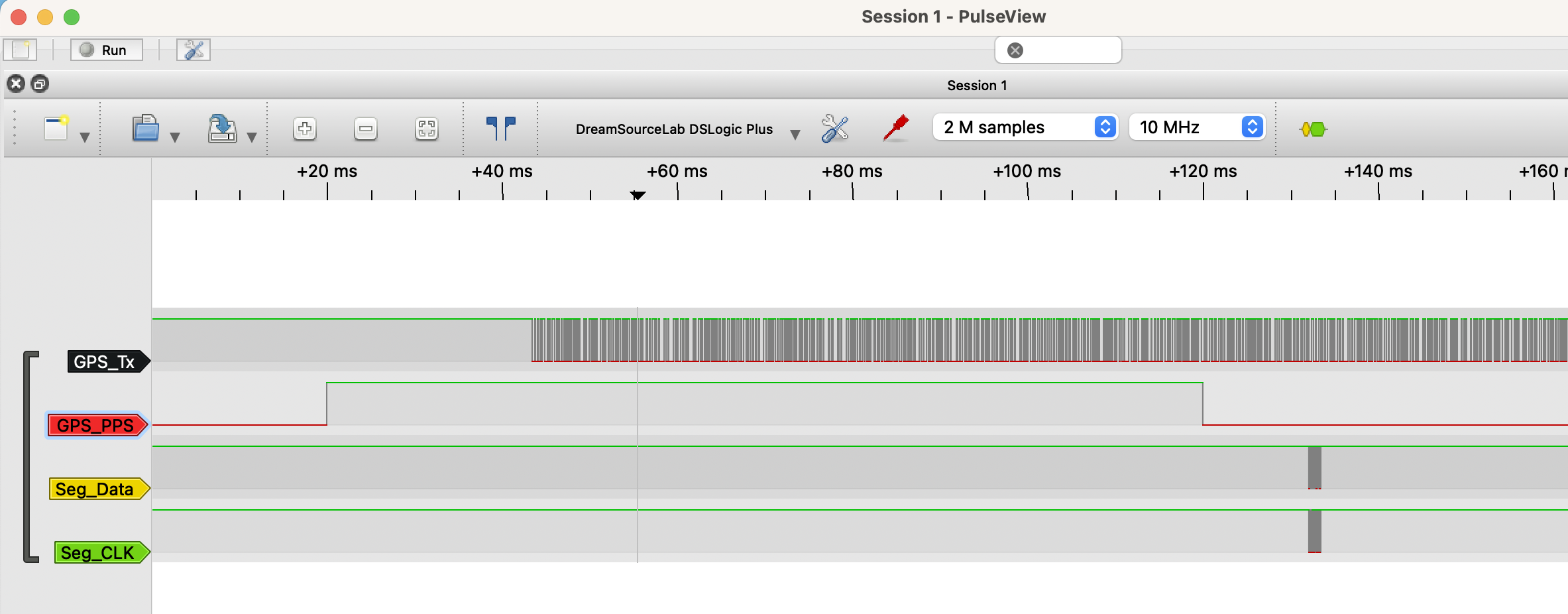
For the display, I assumed that once the data is completly sent, as the point at which it is displayed. There is a delay in the time it takes to be processed at the disaply, but it is small compared to the rest of the processing. For the measurements I am using PulseVeiw with my DS Logic Analyzer, which allows me to see the the exact timeing of these signals, I can then try and summaries them using Wavedrom, to show the communication exchanges rather than signals.
After the 1 PPS signal rises, we see the initial delay to the point when the GPS receiver begins to produce the Serial Messages describing the GPS receivers locations in time and space. This delay changes frequently based on the signal that is received, and is documented on the ublox website which shows the delay as the GPS Position fix calculation.
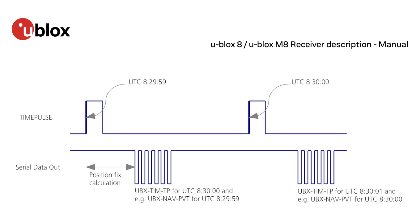
For our purpose on top of the GPS Position fix calculation, there is also a delay in waiting for the GPS message $GNRMC that we are using to extract the time data, then process that text string. This means that we only have to wait until the message we are intreseted in to arrive, at a relitivly slow baud rate of 9600. We can then process the data and not worry about the full range of other messages that we are receiving from the ublox receiver configured with its default settings, with is shown in the wavedrom diagram as ‘T(x)’, and continues after we decode our message.
The update of the display then follows once we have converted the current time into a number of seconds to the next 25th december for this year. For this I used a crude estimate that is based on the number of days in each month, and that we only want to know how many seconds to the next christmas once the new year has started. This falls apart as we aren’t calculating leap years, so may produce some wired behavior I’ve not checked.
//find the number of commas
for( int i=0; i < char_count; i++){
    if(message[i] == ','){
        comma++;
        if(comma == 9){
            date_start = i+1;
        }
    }
}
int day = 10*(message[date_start]-'0') + (message[date_start+1]-'0');
int month = 10*(message[date_start+2]-'0') + (message[date_start+3]-'0');
int year =  10*(message[date_start+4]-'0') + (message[date_start+5]-'0');
printf("UTC Date is: %02i/%02i/%02i\n", day, month, year);
if ( (0 < year)&&  (year <100)){
    if((month <= 12) && (day < 25)){
        //calculate seconds to 25th december
        int days_per_month[] = {31,28,31,30,31,30,31,31,30,31,30,31};
        int day_so_far= 0;
        for(int count=0; count< (month-1); count++){
            day_so_far = day_so_far + +days_per_month[count];
        }
        int end_of_year = (24*60*60)*(365-7-day_so_far-day);
        int end_of_day = (24*60*60)-((hours*60 + mins)*60 +secs);
        seconds_remaining = end_of_year+end_of_day;
    }
    else {
        // between christmas and new year
        seconds_remaining = 0;
    }
else {
    // the case of not being a valid year
    seconds_remaining = 0;
}
Display1A.setValue(double(seconds_remaining),0);
I use the two digit year number as a sanity check to ensure that the date the receiver is producing is a valid number, but that is the only check that is carried out on the data, with it producing a zero output for all values that the number is not valid. This is the same behaviour as between christmas and the new year, which doesn’t help the user understand what is going on, but is a clear way of showing that it doesn’t currently know the actual number of seconds until christmas rather than displaying the wrong number of seconds.
The setup here means that until all the code is executed only at the final line does the current time finally reach the display, which will be other 100ms. The aim is to reduce this time, so I wanted to look at reducing the time from the rising edge of the 1 PPS to that update. Now the fact that I know the time in seconds will increase by a single second at the next rising edge, and use this as a way of updating the display at the rising edge.
For this to work I use two varribles current_pps and last_pps, the current PPS is read from the GPIO pin. This means when the current_pps is high and the last_pps is low we know there has been a rising edge at the start of the 1 PPS signal.
int current_pps = gpio_get(PPS1_PIN);
if (current_pps && !last_pps){
    if (seconds_remaining > 0){
        Display1A.setValue(double(seconds_remaining-1),0);
    }
    else{
        Display1A.setValue(double(0),0);
    }
}
last_pps = current_pps;
For updating the display we can use the pervious number seconds remaining as read from the GPS receiver, but the value from the pervious second, so to get the value for the current second at the PPS I take 1 from seconds remaining that was read when the GPS value was read. As long as the seconds_remaining is greater than zero, we know that the number of seconds, and can update the display using Display1A.setValue(double(seconds_remaining-1),0); just as that happens. This using the pervious GPS message and calculating the number of seconds remaining should give a much faster reaction time to the 1PPs rising edge. the flow of signals is shown in the Wavedrom Signal diagram.
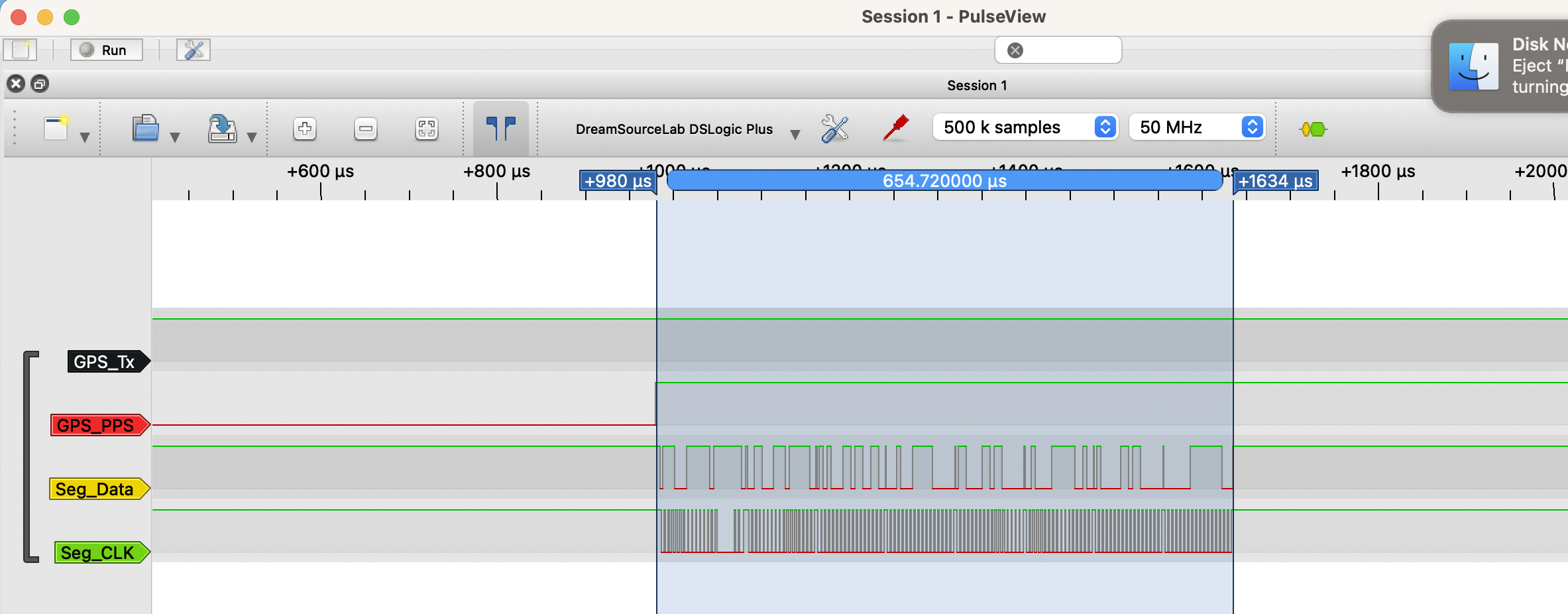
With this new setup we can now see the updated time imediatly after the rising edge on th 1 PPS, this now means that the delay time has been reduced by predicting the current time based on pervious gps data point and the Time Pulse signal.
The improvement can be measured by taking a close look at the signal using the Pulse View. Which we can compared to the pervious measurment made at the start of this post.
Now that the countdown timer is up and running, it just requires the 3D printed case modifying to allow space for the PMod GPS module. With that done the countdown clock will be ready to count down to christmas both this yeaar and next, without the need for any external hardware to provide the current time. This makes it much more flexible and useful, i’m also planning on using the GPS module for a few other projeccts that I have lined up.