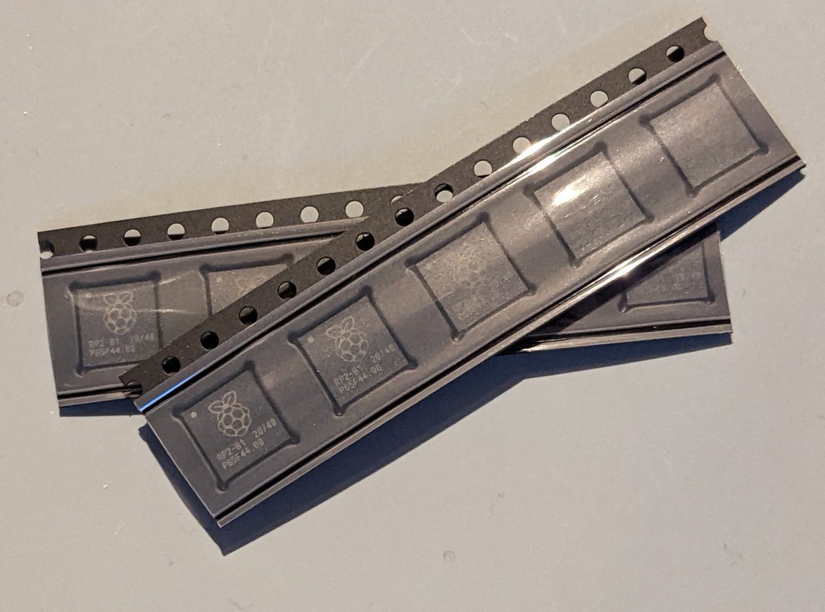
Having perviously built myself a Pico PMod Board around the Raspberry Pi Pico, I wanted to take this to the next level, and build myself a few boards from scratch. So once the orders went live for the RP2040 microcontroller a few months ago, I ordered some, and then did nothing with them for a while.
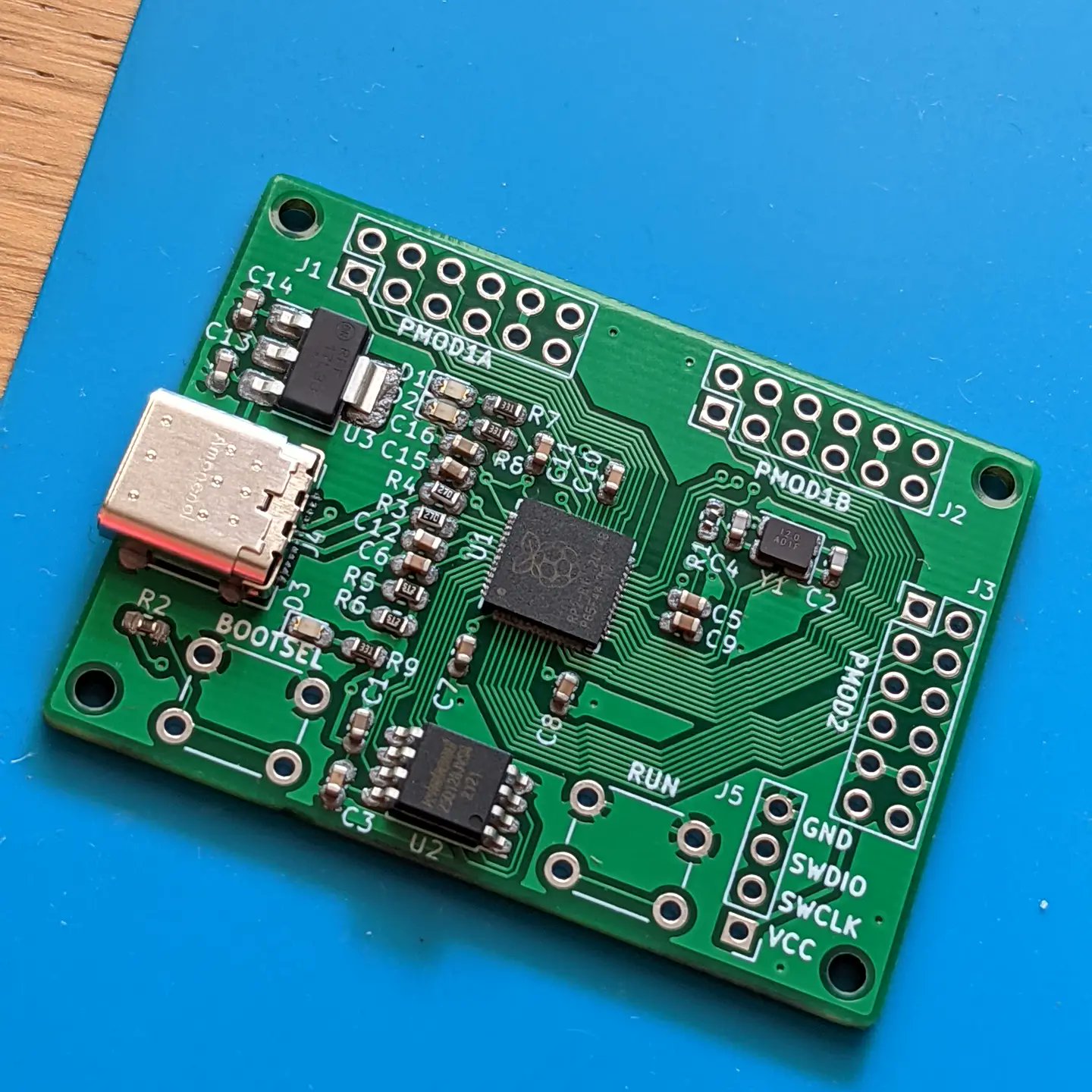
Like many people, I seem to end up with more ideas than time and it took me a little while to get around to this one. What I was looking to create was a simple board with a USB-C connector for my PC and 3 PMod Ports based around the RP2040, I settled on a form factor similar to the IceBreaker FPGA board I have used in the past. This wasn’t for any particular project in mind, but I had enjoyed playing with my Pico PMod Boards so was looking to take it to the next level and improve my PCB building ability along the way.
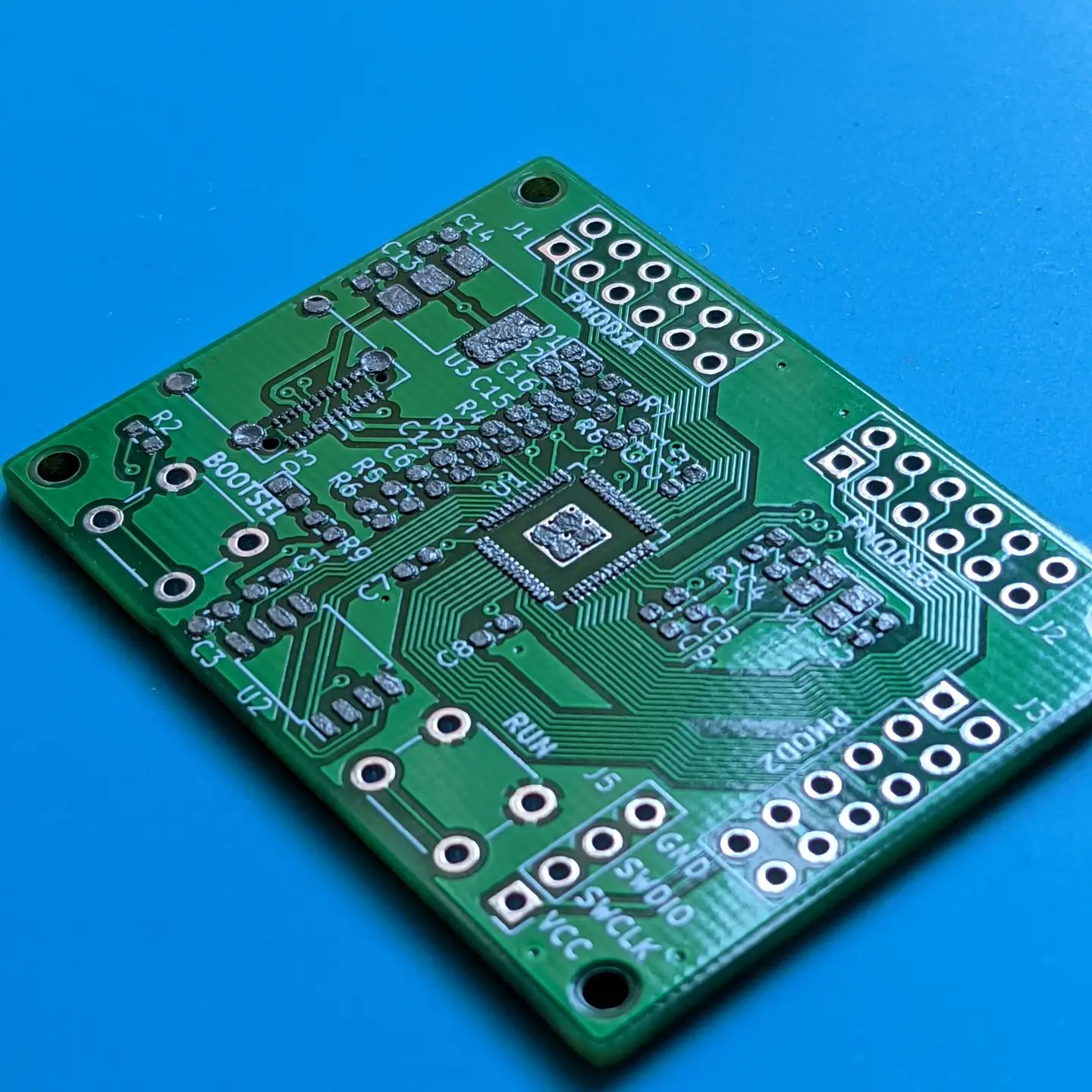
The boards themselves pretty much follow the hardware guidelines, from the RP2040 Datasheet and the supporting documents, using the recommended parts. One thing I did decide that I wanted, was both a Run and Boot select button, as I found these very useful for working with the Pico PMod Board over USB. The boards were designed using KiCAD and I had them made by JLCPCB.
The first set of boards arrived in a couple of weeks, but after building up my first one I hit a few problems, the first was I was missing a few resistor values, so I had to bodge my way around those. I then hit an issue with the USB connection, with my computer not being able to see it. This took me a while to work out what I had done, but it transpired that I had mislabelled my USB connection and had connected the positive and negative data lines the wrong way round, so the USB wasn’t going to work.
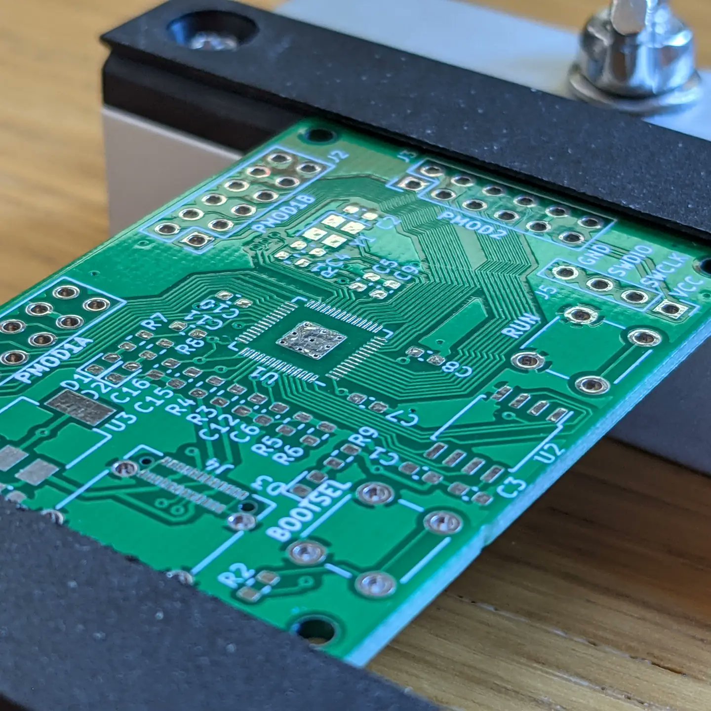
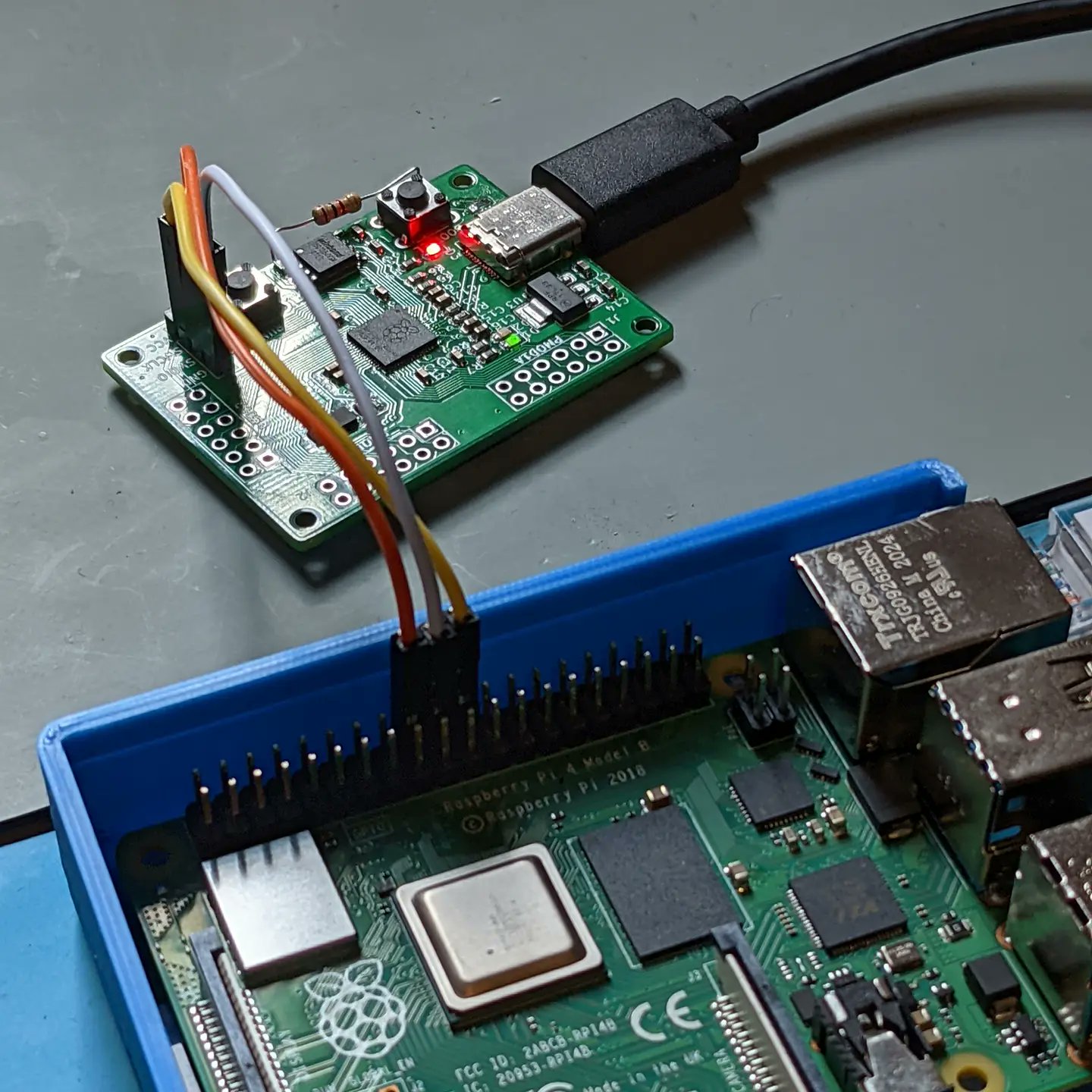
At that moment, I was expecting to have to throw away the boards, but then I thought I would have a go with the debug pins, I had broken these out at the last minute to a connector when designing the PCB. So I thought I should give the debugging interface a try before a scrap them. Having not used the debug interface before, I needed to get the build environment set up on a spare Raspberry Pi 4, and hook up the board, after a few tried working on the correct pins I was able to get a simple “Hello World” example running, flashing the on-board LED using the couple of debug interface.
With the good news that the board seemed to all be working, except the USB issue, I corrected the error, and had a few more PCB’s made by JLCPCB. Having had these ordered they soon arrived, and I was able to build a few more of the boards. One issue I did find is that I am struggling to get consistent results with surface mount soldering on my hot plate. The boards I’m building now are some of the smallest and most complex I’ve tried to build at home so there is always going to be a fair amount of trial and error. Of the second lot of 5 PCB’s ordered 4 were delivered as one was damaged by the PCB manufacturer, I then haven’t been able to get one working, and then two work perfectly after a couple of fixes, while one has a single IO pins which doesn’t seem to be functioning.
The next plan is to start getting some of the PMod Boards I have already purchased and made, hooked up, and get some more working examples with the RP2040 PMod Boards, as well as order a few more boards so I can attempt to improve my surface mount soldering.