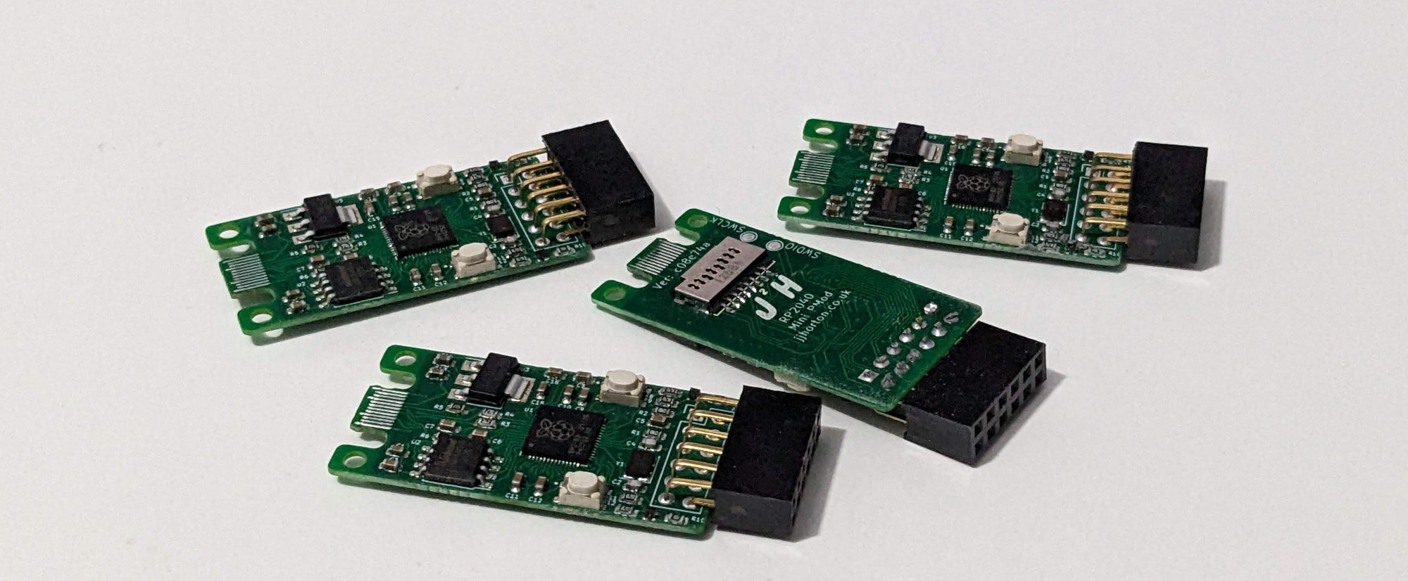
My pervious RP2040 PMod board included 3 PMod Connectors and a USB-C, this has been a great little board for development and testing but there are a couple of issues with this board. The first problem is the size, I would prefer something a bit smaller, with only a single PMod connector. The second is the lack of some additional storage, for logging data to such as GPS positions, and then finally is the cost with the expensive USB-C connector used on my original design being a particular problem, costing more than the RP2040 Micro Controller.
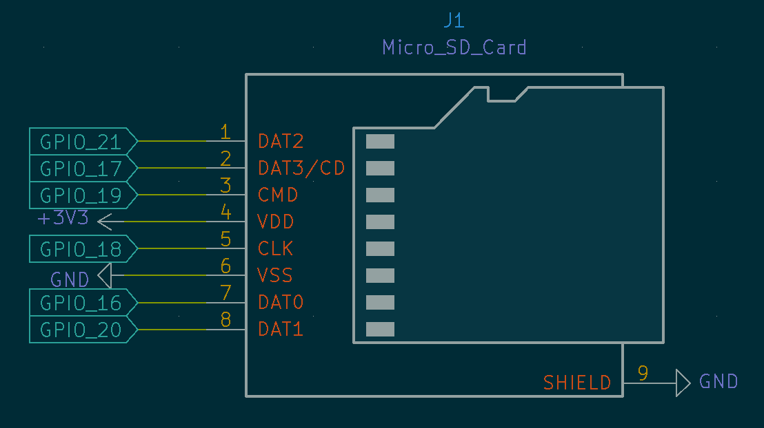
The micro SD card slot is mainly for projects where being able to log data is useful, rather than sending it to a connected PC to be stored on there. I have found this could be useful for a number of of the PMod boards I have, where currently I would just send data over onto a PC to save the data, just logging the data locally provides some better options. I did look at making myself a few little PMod breakout boards, but I soon realized that this wouldn’t work well with the RP2040 boards I use them with a lot at the moment, so hence why this board the Micro SD directly on the back of the board.
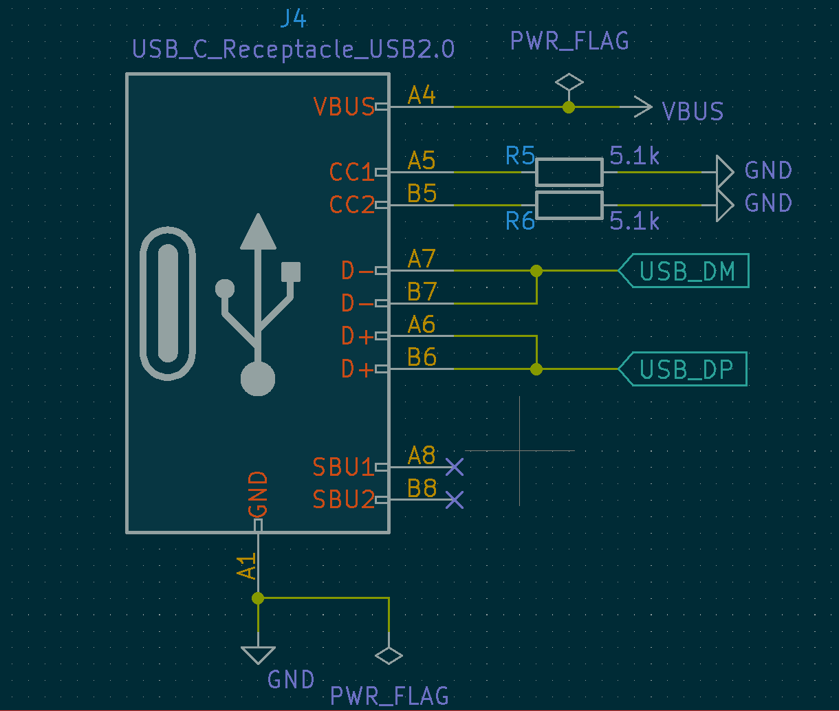
On my RP2040 PMod Board and several other boards I have made with a USB connection I have used a USB-C Connector, USB-C is great, even though I am only making use of the USB 2.0 functionality, and none of the high speed or high power options, using USB-C has proved a reliable way to connector my development boards up to a PC or Power Supply. The USB-C is now often the only port available on my laptops and the option reduce the number of adapters and cables I need to carry it is always a great reason to standardize the boards I personally make around these.
The main disadvantage with USB-C is the cost of the connectors, on the RP2040 PMod Board the USB-C connector costs as much as the RP2040 Micro Controller, making it at the time i made my second batch of boards, the most expensive part on the board. So as a way of reducing this cost, I looked at alternatives to using these expensive connector, and one of the best ones I came across was using the PCB as the connector, this removes the part and allows the PCB to do the task in its place, although this isn’t without its problems.
While I could have spent some time creating a footprint for this part I was able to use the KIcad footprint that someone else had already created, the KiCAD footprint could just be imported and used in place of the old footprint that I previously used. As these are board edge connectors, it is important to consider placement of the connector and allowing space for the cable around the connector.
As the PCB and it’s pads are making up the connector and it will need to slot directly into USB-C cable, we need to considered the PCB thickness, based on the recommendations of a hackaday post, it appeared that using 0.8mm would be fine from JLCPCB even though the size is a little large with the tolerances that USB-C cables allow for, it mates with a cable without any issues.
Prototyping 3D Printing models to test out the functional elements of the design, and comparing with the actual PCB’s. Using the exported models from the kicad and using Cura and my Ender3 3D printer to produce models for testing that the USB connector would be able to fit into the connector, confirming if the PCB thickness was suitable and if I had allowed enough space for most the cables I have at home to be able to fit.
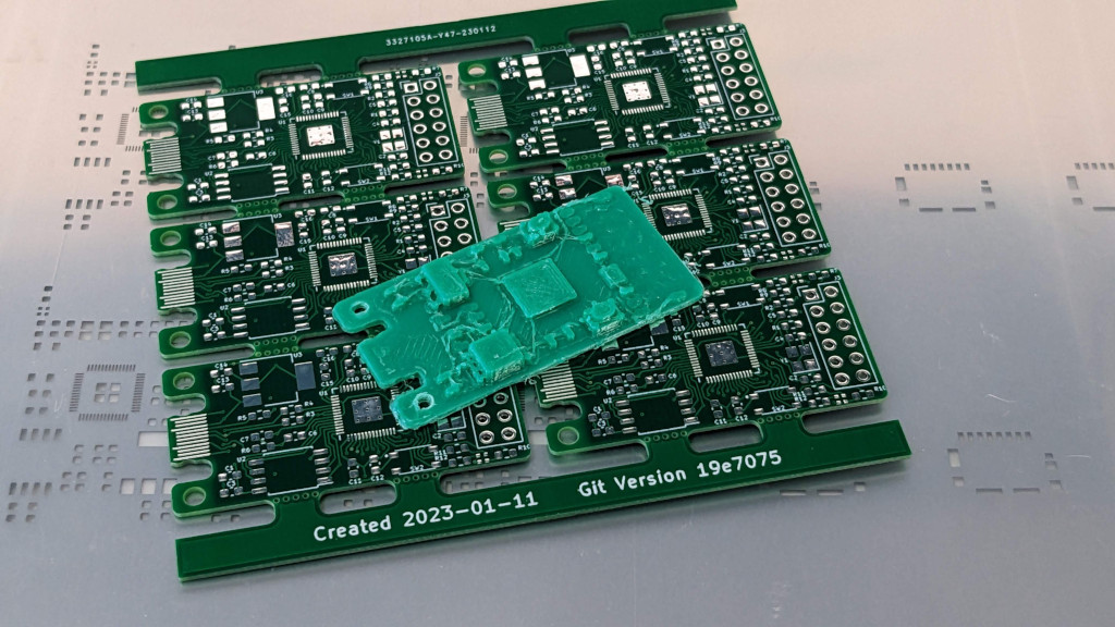
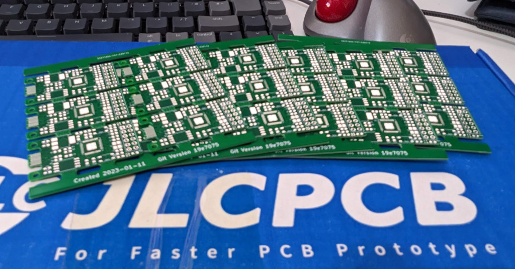
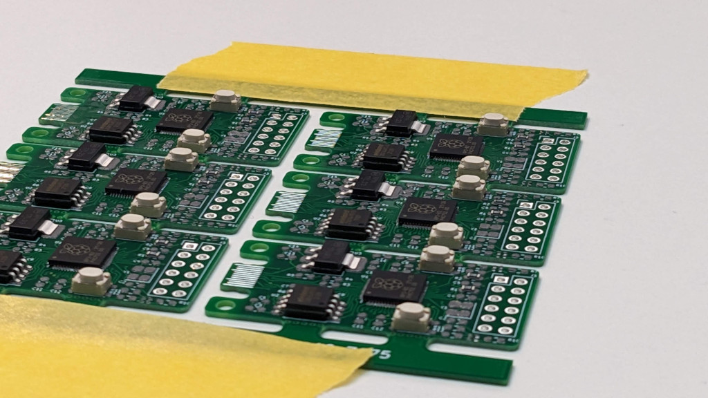
The PCB’s can be assembled individually or in complete panels, but generally I work on complete panels, these boards use many common components on the larger RP2040 PMod board. While even the most simple design changes can give me problems sometimes, as a respin was required to correct an error with the RGB LED’s, that I had wired the wrong way round.
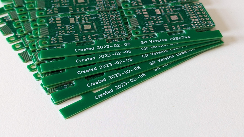
The PCB files are produced automatically using an github action which I write up in my post about Kicad PCB Panels including adding the githash to the board help to keep track of the versions of the board.
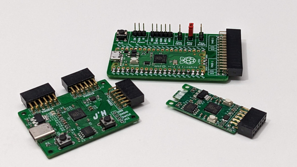
I now have a collection of RP2040 board, all with the same Micro Controller and PMod connector. The mini model is much smaller, which still allowing plenty of compatibility with the standard PMod modules. I hoping the addition SD Card on the back will allow me to play with a few more logging type examples, as well as make some more practical examples with the Thermal Camera and PMod GPS Board.
Useful Links and references that I found while creating these boards are in the table below:
| Reference | Description | Link |
|---|---|---|
| R1 | flexible PCB example | https://github.com/settinger/USB-C_PCB_experiments |
| R2 | usb type c on pcb | https://hackaday.io/project/171381-fluff-m0/log/178674-version-13-and-usb-type-c |
| R3 | with repo: | https://github.com/settinger/USB-C_PCB_experiments |
| R4 | different types: | https://hackaday.io/project/28516-business-card-gamepad/log/72175-pcb-connector-testing |
| R5 | project source of the connector used: | https://github.com/joric/nrfmicro/wiki/PCBA |
| R6 | location of the files from github: | https://github.com/joric/nrfmicro/tree/devel-1.4-pcb-connector/hardware/nrfmicro.pretty |