
After picking up a few Raspberry Pi Pico’s, I was looking for a use for them and I decided to hook up a few of the PMod boards I have from playing around with FPGA. This PMod boards all use the same pinout, of 12 pins, which consists of 8 I/O pins, two 3.3V, and two GND connections on a two row 2.54mm header. I have a few kicking around from a more complex ones, down to a simple 8 DIP switch and a 7 segment display. These are great little boards for connecting to boards like the Raspberry PI Pico when experimenting but the interface with the Pico requires a breadboard to hook them up, so I was looking for a better way to get these PMod’s hooked up.
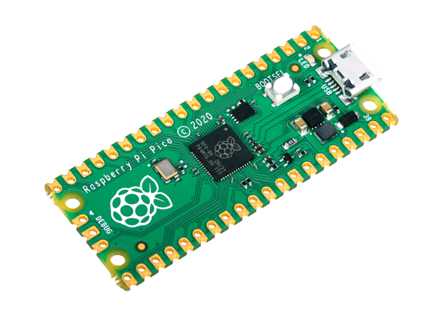
Why bother experimenting with the Raspberry Pi Pico? Well the things that interested me with the Raspberry Pi Pico was not only the low price but also the Programable I/O or PIO on the RP2040 device. This allows you to build small limited sate machines you can set up on some of the outputs, alongside some more traditional Hard IP (SPI/UART/I2C) on the device with a duel core ARM that supports running at a clock rate of over 100MHz. This make it interesting to play with, much as I have been playing around with on FPGA’s in the past few months, without having to get your head around writing lots of HDL such as Verilog or VHDL.
Designing a PCB with KiCAD

Once I had decided to build a PMod Board, I needed to decide the requirements of the board, I decided that I wanted to be able to use the extended PMoD setup, that is used on the colorlite I5 expansion board that I owned, which would allow me to have both a duel PMod connection, and a few extra I/O pins as well as 5V access. I also decided that I would want to be able to connect PMod’s as a host device, as well as connect into an FPGA board like the colorlite I5 . To do this I decided I would break out the 5V pin and 3v3 pin, so we can connect headers when I need to power PMod devices from the Picos power supply, or disconnect them when I want to use the USB connection.
Other pins I looked to break out to headers was the analog inputs, and the 3v3 enable pin. This gives me more flexibility when choosing how to power the Pico when it is connected up as a client device to one of the FPGA boards. Another popular feature I added was connecting up the Run pin to a button which pulls it to ground, allowing the Pico to be safely reset, when I want to upload a new program.


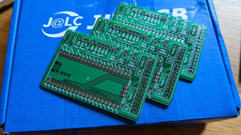
Once all the requirements were captured in the schematic, it was a quick task to layout the board. Thankfully, a footprint and schematic symbol that match the Pico requirements were available in a library which could be loaded into KiCAD that someone has made available on Github, which greatly speed up getting these boards made up. With the simple boards made up
Building a counter example
With the boards made and tested, I was now ready to start hooking up a simple PMod, and getting my head round writing C/C++ again, as it has been a while.
The process for compiling c/c++ for the Raspberry Pi Pico is really well documented, and the Raspberry Pi Website is a great resource in getting everything set up on matter on what you are using to compile the software. I did find the examples repo, a bit intimidating when wanting to build something from scratch for the cmake files but there were plenty of back to basics examples avalible from a quick google search.
The first example that I wanted used the PMod 7 segment display, and I wanted to display a counter that increments once per second. The first set was getting a suitable cmake file setup, this includes all the information the Pico SDK needs to build my project, this is a simple project with no real external dependancies other the the pico_stdlib library and the code will be in my file main.c, which keeps this file nice and simple.
make_minimum_required(VERSION 3.12)

# include(pico_sdk_import.cmake)
include($ENV{PICO_SDK_PATH}/pico_sdk_init.cmake)

# Change your executable name to something creative!
set(NAME pico-pmod)

project(${NAME} C CXX ASM)
set(CMAKE_C_STANDARD 11)
set(CMAKE_CXX_STANDARD 17)

# Initialize the SDK
pico_sdk_init()

# Add your source files
add_executable(${NAME}
    main.c
)

# Don't forget to link the libraries you need!
target_link_libraries(${NAME}
	 pico_stdlib
)

# create map/bin/hex file etc.
pico_add_extra_outputs(${NAME})
The next task is building up our program, first up is importing the standard library’s, and at this point we will also set up some variables that we will need. One of the main once here are the SEVEN_SEGMENT_PINS array of constants, these list of pins can be swapped by changing the LCD_DISPLAY value which is the same as the PMod output connector of the custom PCB.
#include "pico/stdlib.h"

#define LCD_DISPLAY 1
#define LOOKUP_TABLE_LENGTH 50

#if (LCD_DISPLAY==0)
	//if plugged into pmod1
	const uint SEVEN_SEGMENT_PINS[] = {9,11,13,15,8,10,12,14};
#else
	//if plugged into pmod0
	const uint SEVEN_SEGMENT_PINS[] = {21,19,17,3,20,18,16,2};
#endif
The first function we define is a nice simple one, this is used to setup the output pins, initialising them as GPIO (General Purpose Input Output) Pins, setting the direction for each of them as outputs and setting them each as a low value. This function is called as part of the setup process, and is only used once.
int setup_display(){
	for(int x = 0; x<8; x++) {
			gpio_init(SEVEN_SEGMENT_PINS[x]);
			gpio_set_dir(SEVEN_SEGMENT_PINS[x], GPIO_OUT);
			gpio_put(SEVEN_SEGMENT_PINS[x],0);
	}
}
The function is to display the values on the seven segment display, to do this we create an array with each row corresponding to the pins that we need to turn on to display the corresponding number, this array is characters[] array, with the first value of the unit8 always set to zero and ignored the rest define each of the segments on the seven segment display.
int set_display(uint num1, uint num2){

	// the table used to set the charcter to be on
	uint8_t characters[] = {0b01000000,	// 0
							0b01111001,	// 1
							0b00100100,	// 2
							0b00110000,	// 3
							0b00011001,	// 4
							0b00010010,	// 5
							0b00000010,	// 6
							0b01111000,	// 7
							0b00000000,	// 8
							0b00011000,	// 9
							0b00001000,	// A
							0b00000011,	// B
							0b01000110,	// C
							0b00100001,	// D
							0b00000110,	// E
							0b00001110};// F


	// set the display values
	//for the first digit
	for(int x = 0; x<7; x++) {
		gpio_put(SEVEN_SEGMENT_PINS[x], (characters[num1] >> x) & 1U);
	}

	gpio_put(SEVEN_SEGMENT_PINS[7], 1);
	sleep_ms(10);

	//for the second digit
	for(int x = 0; x<7; x++) {
		gpio_put(SEVEN_SEGMENT_PINS[x], (characters[num2] >> x) & 1U);
	}

	gpio_put(SEVEN_SEGMENT_PINS[7], 0);
	sleep_ms(10);

	return 0;
}
The two displays are multiplexed together, so the output pins for this loop are set using the gpioput() function, cycling through the elements of the character with the x variable and writing the binary values to the pins from the characters array using the command (characters[num1] >> x) & 1U). We then let this display remain on for a few milliseconds using the function sleep_ms(10); before then setting the pin for the multiplexer gpio_put(SEVEN_SEGMENT_PINS[7], 0); and repeating the process for the other character with the num2 value.
The main function then pulls these two functions together, setting up the display and the counters that we will display. the counters are all initialised to zero, after we have called out setup_display(); function. The main counter then cycles around 50 times, before we then increment counter1, once counter 1 has reached 15 (displayed on the screen as e), we then increment the 2nd digit. This results in the counter incrementing approximately once per second.
int main() {

		// setup the outputs for the display
		setup_display();

		//initalise the counters used to count up on the display

		uint counter = 0;
		uint counter1 = 0;
		uint counter2 = 0;

		// main loop for updating the display and updating the counter
		while (true) {
			set_display(counter1, counter2);
			counter++;

			if(counter>PAUSE_LENGTH){ counter = 0; counter1++;}
			if(counter1>15){ counter1=0; counter2++;}
			if(counter2>15){ counter2=0;}
    }
}
The next set is building the code i have written, this is a standard process which is well documented in the SDK documentation. As I tend to stick to the terminal when working on my Macbook, I just type the commands in which is a simple as:
 export PICO_SDK_PATH=../pico-sdk
 mkdir build
 cd build
 cmake ..
 make -j4
With the code build successfully, we can then copy it onto the Pico, with the PMod Board this is now easier and doesn’t require unplugging the Pico. Instead we can hold down the run button, then press the Boot button. the releasing the Run followed by Boot button and the Pico appears on as a removable drive ready for us to drop the pico-pmod.uf2 file onto it, at which point it begins running our program.
What next
The next challenge will be building some examples with PIO, working with a few more PMod type devices. One error that needs fixing, 5v and GND pin wrong way round, in order to match the Colorlite i5 FPGA Dev Board that I have. I’m planning on building a few custom PMod boards so I can develop and test both FPGA based examples and Pico Based examples, to improve my coding ability for coding on both.