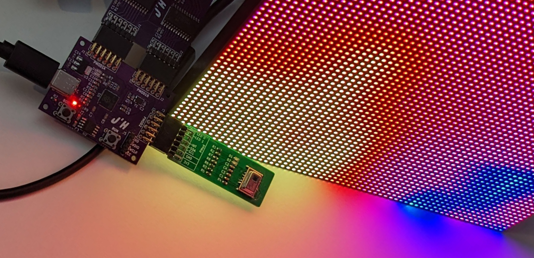
Having picked up a couple of LED Matrix’s from aliexpress that I thought should finally be put to some good use, having perviously made up some IR Thermal camera PMods I thought it would be a great idea to hook them up together, and have a nice big display with the array from these sensors scaled up.
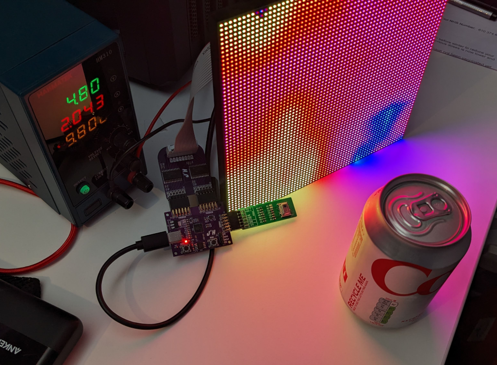
The hardware that is needed mostly relies on what I had already built, mainly the RP2040 PMod Board and the PMod IR Camera, but there is the need for a board to interface between the HUB75 display and the RP2040 PMod board. While for initial testing it was not problem to drive the display directly, i decided to invest some time to make some proper interface boards.

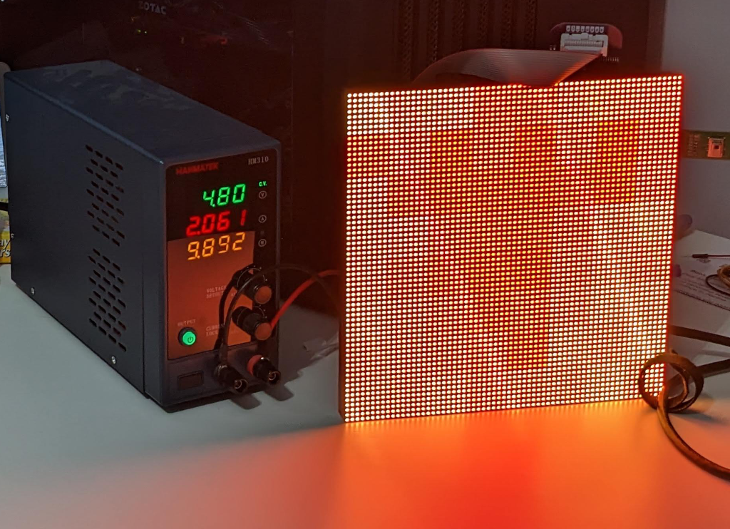
The proof of concept was to hook up the display directly to the RP2040 PMod Board which was completed using some short wires and a HUB75 example from the Raspberry Pi Pico github Repository. This allows for using a static preprocessed image when directly attached up, but this is a hacky solution, so hence the need for a more permanent solution.
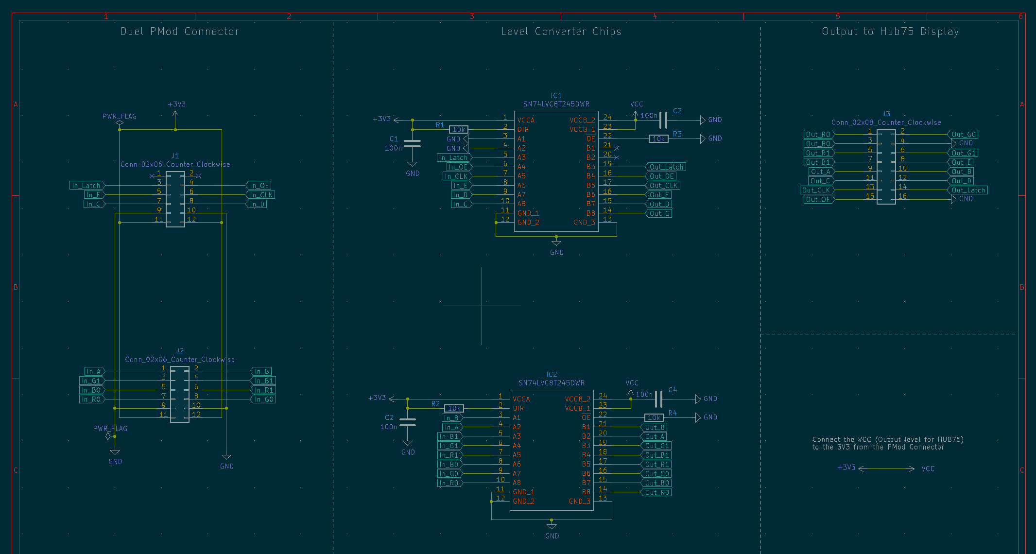
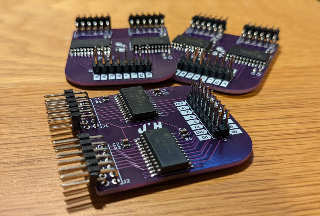
The design uses a SN74LVC8T245 which is an eight bit non-inverting bus transceiver, this is based loosely on a board design I saw used with the iceBreaker FPGA boards, but I use a larger variant of the chip because it is easier to solder and work with. The Schematic was designed with KiCAD as with my other recent PCB’s.
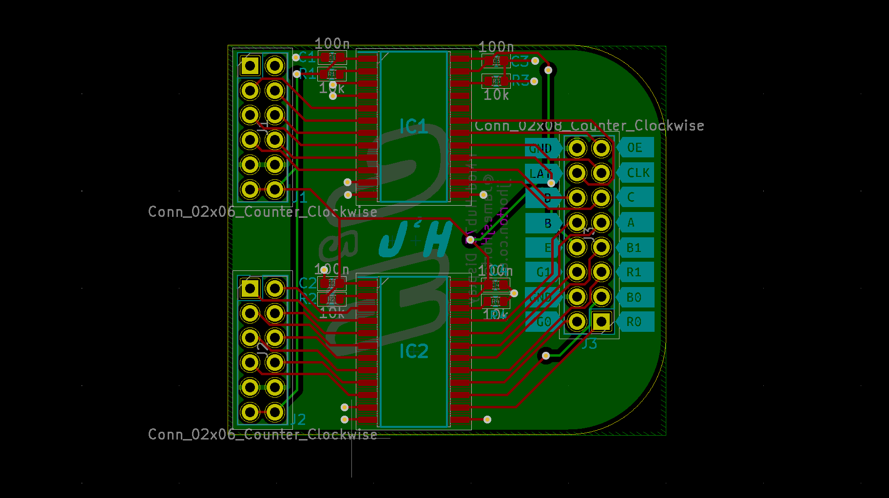
The PCB’s where then produced by JLCPCB in the excellent purple colour, for the labels this time I made use of KiBuzzard which allows me to generate the labels I use to show the signals on the hub75 connector.
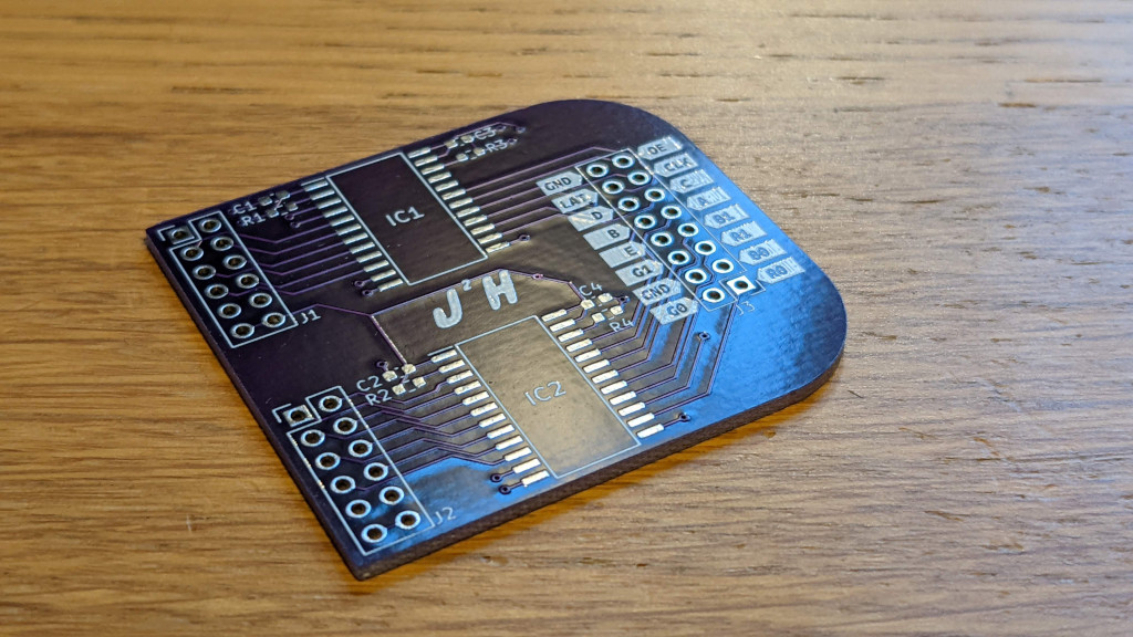
The PCB’s were assembled by hand using a solder stencil from JLCPCB that I used with my aliexpress hot plate, the results are pretty good and I managed to get all five examples I built fully working.
With that completed and the previous attempts having creating an example that displays the values on a 8x8 neopixel display, which has many of the key features, but now I just needed to scale up the image.
The first attempt to scale up the image to fit on the 64 by 64 LED matrix, worked by splitting up the pixels into an 8x8 grid, where each square controlled by the single values from the IR grid array. Each square has 8x8 indervidual RGB LED’s, that are controlled, this is simple to implement in c and can be completed by just a few loops.
//upscale in 8x8 blocks of color
for (int i = 0; i<8; i++){
    for (int j = 0; j<8; j++){
        for(int a = 0; a < 8; a++){
            for(int b = 0; b< 8; b++){
                upscaled_temps[(((j*8)+b)*WIDTH)+((i*8)+a)] = my_temps[(j*8)+i];
            }
        }
    }
}
The result is an image that fills the LED matrix, and help make it easy to see the image, but there are some limitations of this mainly how easy it is to interpret the image. The blocky nature of the image limits how useful it is, and is essentially just a scaled up version on the Neopixel example.
The next attempt I wanted to look at was smoothing the image, to make it appear as though the image has a much higher resolution. This removes the blocky values that I created before and attempts to guess the values in between the points, creating a smooth line between them, the 2d linear interpolation is often referred to Bilinear interpolation
For this I use a simple two step process:
- taking each row of 8, and then upscaling them to a row of 64.
- Then use the values from the expanded row to do the same for each column.
The first step can be summaries with a simple formula, where for each pair of values we got from the sensor we just need to create 7 steps, which are done with the formula:
f(x)=x0+n*(x1 - x0)
Where x0 and x1 are the points either side of the position we want to add in, and the n is the point that we want to add which in this case is n/8 steps, moving along the line for each value of n up to 8. The only variation of this formula is on the last run where we use a slightly shorter edge so that line including the actual measurements is included on this display. The main complication for implementation in C for running on the Pico is that we need to deal with the array the data is saved in only being 2D, and no where to find our 3D values correctly:
for (int i = 0; i<8; i++){
    for (int j = 0; j<8; j++){
        if(i<7){
            //first cell is the actual value from the sensor
            upscaled_temps[(((j*8))*WIDTH)+((i*9))] = my_temps[(j*8)+i];

            //calculate inter factor between each of the pixelsa
            float i_diff = (my_temps[(j*8)+(i+1)] - my_temps[(j*8)+i])/9;

             for(int a = 1; a < 9; a++){
                float step = i_diff*a;
                upscaled_temps[(((j*8))*WIDTH)+((i*9)+a)] = my_temps[(j*8)+i] + step;
            }
        }
        else{
            upscaled_temps[(((j*8))*WIDTH)+(((i+1)*8)-1)] = my_temps[(j*8)+i];
        }
    }
}
Completing the columns is just a simple case of applying the same principles from the rows to our freshly expanded array which is 64x8, so that it will become 64x64. We just need to deal with the special case of the end pixels again where the gap is different:
        for (int i = 0; i<(WIDTH); i++){
            for (int j = 0; j<8; j++){
                for(int a = 0; a < 8; a++){
                    float diff = 0;
                    float ref_start;
                    float ref_end;
                    if (j==7){
                        //end pixels
                        ref_start = upscaled_temps[(((j*8))*WIDTH)+i];
                        ref_end = upscaled_temps[((((j)*8)-1)*WIDTH)+i];
                        diff = (ref_end-ref_start)/8;
                    }
                    else {
                        //middle pixels
                        ref_start = upscaled_temps[(((j*8))*WIDTH)+i];
                        ref_end = upscaled_temps[((((j+1)*8))*WIDTH)+i];
                        diff = (ref_end -ref_start)/8;
                    }

                    for(int b = 1; b < 8; b++){
                        float step = diff*b;
                        upscaled_temps[(((j*8)+b)*WIDTH)+i] = ref_start + step;
                    }
                }
            }
        }
With that completed we can now send the image we h=have generated to the display, as the sensor only provides an image at a maximum rate of 10 frames per second there isn’t much of a need to optimize this in this example.
I may in the future have a look at finding a way to implement bicubic interpolation, as that would improve the image that is produced, but also I would like to mount the camera and RP2040 onto the back of the screen with a single power supply so only a single power supply is needed, but all that is a task for another day.